5 centering weights (g1, g2, g3, g4, g5), 6 gravity weights (s1, s2) – VEGA VEGAFLEX series 80 Centering User Manual
Page 14
14
2 Mounting
Centering • for VEGAFLEX series 80
44967-EN-131119
Note:
The retaining rings can be moved only in one direction. If you have
already passed the desired position, cut the retaining ring with a side
cutter. Use a new retaining ring.
2.5 Centering weights (G1, G2, G3, G4, G5)
1
2
3
4
5
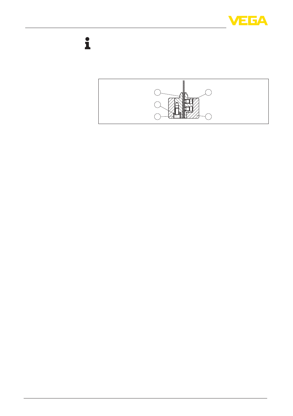
Fig. 11: Mounting the centering weight (G1, G2, G3, G4, G5)
1 Threaded pins
2 Centering weight
3 Fixing screw - centering weight
4 Retaining washer (Nordlock
®
)
5 Inner insert
1. Select the centering weight (2) according to the tube inside diam-
eter.
2. Loosen the fixing screw (3) and remove the inner insert (5) from
the centering weight (2).
3. Lead the cable of the probe through the inner insert (5) until it
ends flush with the lower side of the inner insert (5).
4. Fasten the cable of the probe with the two threaded pins (1).
Tighten the pins (1) with a torque of 7 Nm (5.16 lbf ft).
5. Place the centering weight (2) from below onto the inner insert
(5).
6. Insert the fixing screw (3) and the two retaining washers (4) into
the centering weight (2).
7. Fasten the inner insert (1) with the fixing screw (2) on the center-
ing weight (3).
8. Tighten the fixing screw (3) with a torque of 7 Nm (5.16 lbf ft).
9. If you retrofit a centering weight, you have to select the correct
probe type in the instrument (e.g. cable ø 4 mm with centering
weight). If the probe length has changed, you have to enter the
new probe length in the instrument and then carry out the adjust-
ment again (see also "Setup steps, Carry out min. adjustment -
Carry out max. adjustment").
2.6 Gravity weights (S1, S2)
The following process describes the mounting of the gravity weight on
the cable of the probe.
Mounting the gravity
weight