4 mounting, 1 general instructions – VEGA VEGACAP 27 - Relay (DPDT) User Manual
Page 10
10
4 Mounting
VEGACAP 27 • - Relay (DPDT)
33758-EN-130916
4 Mounting
4.1 General instructions
Make sure that all parts of the instrument coming in direct contact
with the process, especially the sensor element, process seal and
process fitting, are suitable for the existing process conditions, such
as process pressure, process temperature as well as the chemical
properties of the medium.
You can find the specifications in chapter "Technical data" and on the
nameplate.
In general the level switch can be mounted in any position. The instru-
ment must be mounted in such a way that the probe is at the height of
the requested switching point.
Before beginning the welding work, remove the electronics module
from the sensor. By doing this, you avoid damage to the electronics
through inductive coupling.
With threaded versions, the housing must not be used to screw in the
instrument. Applying tightening forces on the housing can damage its
internal parts.
Use the hexagon for screwing in.
Use the recommended cables (see chapter "Connecting to power
supply") and tighten the cable gland.
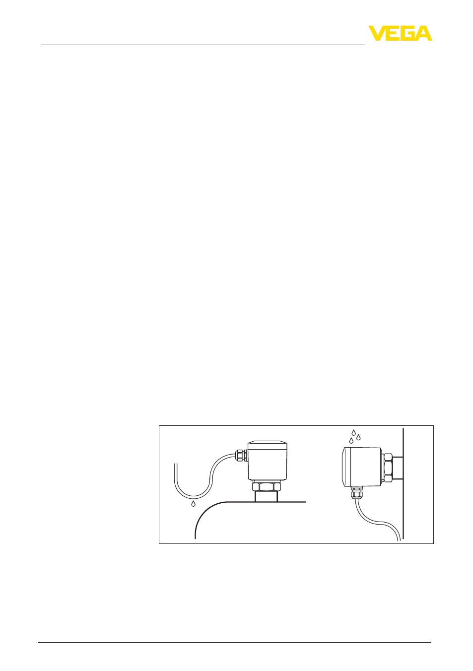
You can give your VEGACAP 27 additional protection against mois-
ture penetration by leading the connection cable downward in front of
the cable entry. Rain and condensation water can thus drain off. This
applies mainly to outdoor mounting as well as installation in areas
where high humidity is expected (e.g. through cleaning processes) or
on cooled or heated vessels.
Fig. 3: Measures against moisture penetration
Do not hold VEGACAP 27 on the probe. Especially with heavy flange
versions or long rod versions, the sensor can be damaged simply by
the weight of the instrument.
Suitability for the process
conditions
Switching point
Welding work
Handling
Moisture
Transport