3 wiring plan, 4 switch on phase – VEGA VEGAWELL S 51 User Manual
Page 19
Connection via VEGABOX 02
Proceed as follows:
1
Snap VEGABOX 02 onto the carrier rail or
screw it to the mounting plate
2
Loosen the cover screws and remove the
cover
3
Push the cable into VEGABOX 02 through the
cable entry
4
Loosen the screws with a screwdriver
5
Insert the wire ends into the open terminals
according to the wiring plan
6
Tighten the screws with a screwdriver
7
Check the hold of the wires in the terminals by
lightly pulling on them
8
Tighten the compression nut of the cable entry.
The seal ring must completely encircle the
cable
9
Connect the supply cable according to steps 3
to 8
10 S
crew the housing cover on
The electrical connection is finished.
4
.3
Wiring plan
Direct connection
4
1
2
2
3
Fig. 14: Wire assignment, suspension cable
1
Blue (-): to power supply or to the processing system
2
Brown (+): to power supply or to the processing system
3
Shielding
4
Breather capillaries with filter element
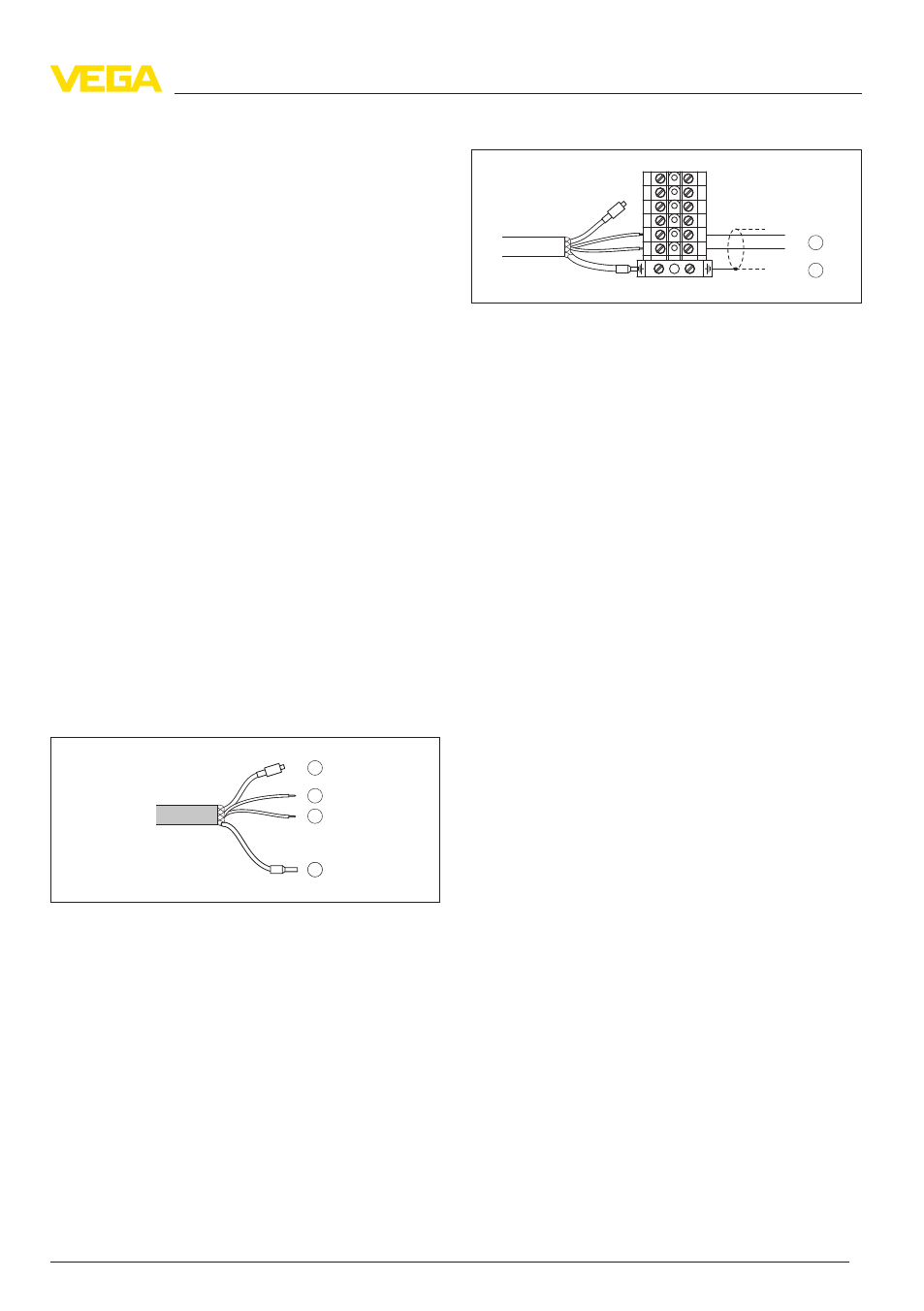
Connection via VEGABOX 02
1
2
–
+
1
2
3
4
5
6
1
2
3
4
5
6
Fig. 15: Terminal assignment VEGABOX 02
1
To power supply or the processing system
2
Shielding
3
4
.4
Switch on phase
After connecting VEGAWELL S 51 to power supply
or after a voltage recurrence, the instrument carries
out a self-check:
l
Internal check of the electronics
l
4 … 20
mA output jumps to the failure signal
The insturment delivers after this run-up period a
current of 4 … 20 mA to the cable. The value
corresponds to the actual level as well as to
settings already carried out, e.g. the factory setting.
VEGAWELL S 51
19
Connecting to power supply
32946
-
01
-
101123