Basic properties of profibus fms and profibus dp, Protocol architecture – VEGA VEGASCAN 850 Profibus DP signal output User Manual
Page 21
Profibus DP signal output VEGASCAN 850
21
Basic properties of Profibus FMS and
Profibus DP
PROFIBUS determines the technical and
functional properties of a series field bus
system, through which distributed, digital
field automation instruments in the lower (sen-
sor/actuator level) up to the medium (cell
level) power range can be connected.
PROFIBUS distinguishes between Master
and Slave instruments.
Master instruments
determine the data
traffic on the bus. A master can send mes-
sages without external request, provided the
master is authorised for bus access. In the
Profibus protocol, Masters are also called
active participants.
Slave instruments
are low-expenditure
peripherals. Typical Slave instruments are
sensors, actuators, transmitters. They do not
receive authorisation for bus access, i.e. they
are only allowed to acknowledge received
messages or transmit messages to a Master
on its request. Slaves are also called passive
participants. They require only a small portion
of the bus protocol, and as a result, a very
low-expenditure implementation of the bus
protocol is ensured.
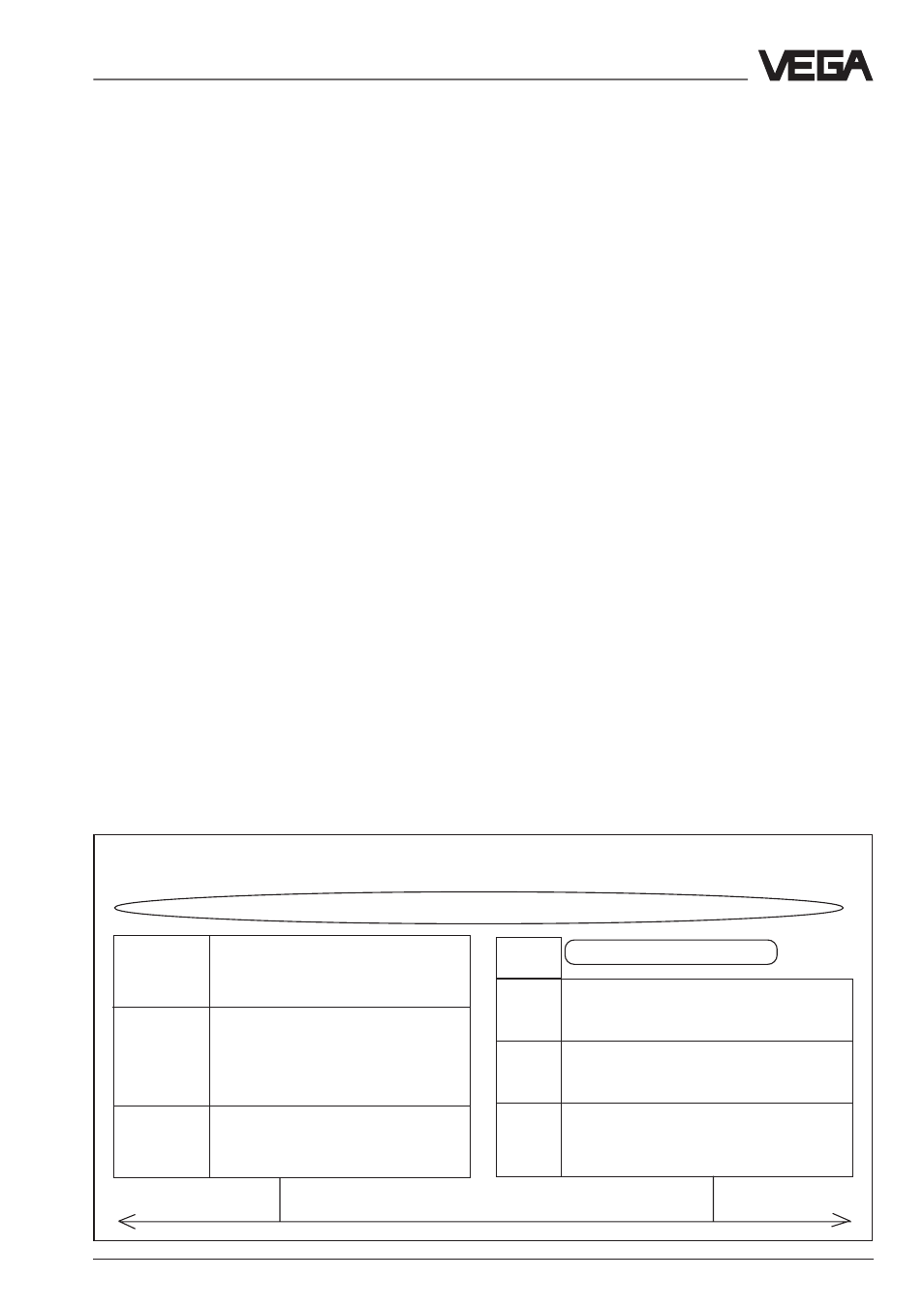
Protocol architecture
PROFIBUS is based on a number of ap-
proved international and national standards.
The protocol architecture orients itself on OSI
(Open System Interconnection) multilayer
system, according to the international stand-
ard ISO 7498. The architecture of the Profi-
bus FMS and the Profibus DP protocol is
shown in figure 2.
PROFIBUS layer 1 (Physical Layer)
The application range of a Fieldbus system is
mainly determined by the selection of the
transmission medium and the physical bus
interface. Beside the demands on transmis-
sion reliability, the expenditures for procure-
ment and installation of the bus cable are of
great consequence. That’s why the Profibus
standard makes provision for different ver-
sions of transmission technology, while keep-
ing to a single, uniform bus protocol.
PROFIBUS layer 2 (Data Link Layer)
The second layer of the OSI multilayer sys-
tem realises the functions of the bus access
control and data backup, as well as the man-
aging of transmission protocols and tel-
egrams. Layer 2 is called Fieldbus Data Link
(FDL) with PROFIBUS.
Protocol architecture
Profibus DP
Profibus FMS
Application process
DIN (E)
User-Interface
PNO
Application Layer Interface (ALI)
19 245
Profile
part 3
Direct-Data-Link-Mapper (DDLM)
DIN
Application-Layer (7)
19 245
Fieldbus Message Specification (FMS)
Layer 3 to 7
part 2
Lower Layer Interface (LLI)
is not defined
Layer 3 to 6
is not defined
Subset of
Data-Link-Layer (2)
DIN
Data-Link-Layer (2)
DIN 19 245
Fieldbus Data Link (FDL)
19 245
Fieldbus Data Link (FDL)
part 1
Physical-Layer (1)
part 1
Physical-Layer (1)
Profibus transmission medium
Supplement