2 terminal assignment, 3 connection example, Electrical connection – VEGA D98 Pressure transmitter User Manual
Page 9
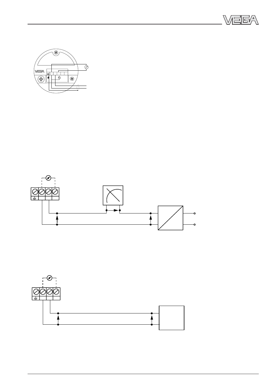
Pressure transmitter D98
9
+
+ – –
1 2 3
–
Oscillator is supplied by a PLC with active input circuit
Evaluation is carried out via PLC.
Ammeter for on-site check
connection terminals
pressure transmitter
U
K
U
H
memory program-
mable control
4 … 20 mA
4.3 Connection example
The following examples are valid for a direct connection to the terminals of the pressure trans-
mitter. When the external connection housing is used, the connections are made to the appro-
priate terminals of the housing.
The hydrostatic pressure transmitter D98 is adjusted to the indicated measuring range by
VEGA and has no adjustment option.
Oscillator is supplied by a power supply unit
The adjustment is made via the indicating instrument.
~
1 2 3
+
–
+ – –
analogue / digital indicating
instrument
Ammeter for on-site
control
connection terminals
pressure transmitter
power supply unit
U
K
U
A
U
H
4 … 20 mA
4.2 Terminal assignment
Electrical connection
4...20mA
12...36 V DC
+
-
-
1 2 3 4 5
+
-
+
4-20mA
control unit 4 … 20 mA
energy supply
12 … 36 V DC
Notes:
An ammeter for on-site check of the output current can be connected to the terminals 1 and 3.
This measurement can be carried out during operation without interruption of the mains sup-
ply.