VEGA VEGATOR 532 Ex User Manual
Page 20
Two potentiometers for switching point adaptation are located on the
front plate of the signal conditioning instrument. With this potenti-
ometer you can adapt the measuring system to the conductivity of the
medium separately for each channel.
Use a small screwdriver to carry out adjustments on the potentiometer.
One slide switch per channel is located on the circuit board of the
signal conditioning instrument. Set the requested mode before
inserting VEGATOR 532 Ex because the switch will no longer be
accessible in assembled condition.
l
A - Max. detection or overflow protection
l
B - Min. detection or dry run detection
Selection of the mode
You can set mode A or B by means of the selection switch.
Preferrably as overflow protection, compulsory as overfill protection.
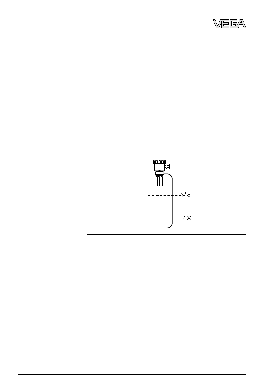
1
2
3
Fig. 11: Mode A - Overfill protection
Means with covered max. electrode:
l
Relay (channel 1) denergizes, connection d10/b10 connected
through relay
l
Transistor output (channel 1) blocks
l
Control lamp output (channel 1) extinguishes
Means with uncovered max. electrode (level detection) or min.
electrode (two-point control):
l
Relay (channel 1) energizes, connection d10/z10 connected
through relay
l
Transistor output (channel 1) conducts
l
Control lamp output (channel 1) lights
Potentiometer for
switching point adjust-
ment
DIL switch - Mode
Mode A
20
VEGATOR
532 Ex • Signal conditioning instrument
6 Set up
23435
-EN
-090130