Parts and functions 2. terminal descriptions, 12vdc power output, Power ground – V-Tech IP-MR18 Manual User Manual
Page 3: Common contact of the relay, Exit button connection port, Usb-rs485 communication terminal negative, Usb-rs485 communication terminal positive, Power input for door station, Bus output(including data, audio and video signal), For updating the language and ui of door station
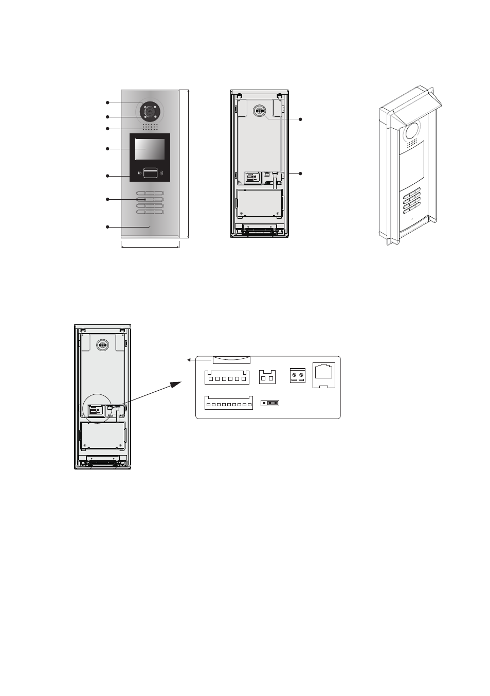
1.Parts and Functions
2. Terminal Descriptions
Camera Lens
Night View LED
Speaker
Adjustable Camera
Connectiong Port
With rainy cover
350 mm
128 mm
1
2
3
6
5
4
7
8
9
#
0
*
RF CARD
LCD Screen
ID Card Window
Digital Keypad
Microphone
1
2
3
T/R -
CN-LK
T/R+
J/KMB
JP-LK
RS-485
P -
P+
JWP
JWB(OUT)
SD Card Slot
EB+
EB-
N.O
LK+
LK-
+12V
1
2
3
1
2
3
•
+12V:
12VDC power output.
•
LK-(GND):
Power ground.
•
LK+(COM):
Common contact of the Relay .
•
NO.:
Normally open contact of the Relay (Can be set to be normally closed)
•
EB+:
Exit button connection port.(Short EB+&EB- to unlock)
•
EB-:
Exit button connection port.
•
JP-LK:
For electronic lock safety type setting(refer to Door Station Lock Connections).
•
T/R-:
USB-RS485 communication terminal negative.
•
T/R+:
USB-RS485 communication terminal positive.
•
JWP(P+,P-):
Power input for door station
•
JWB(OUT):
BUS Output(Including Data, audio and video signal)
•
SD Card Slot:
for updating the language and UI of door station
-1-