Veris Verabar V200S Installation Instructions User Manual
Page 3
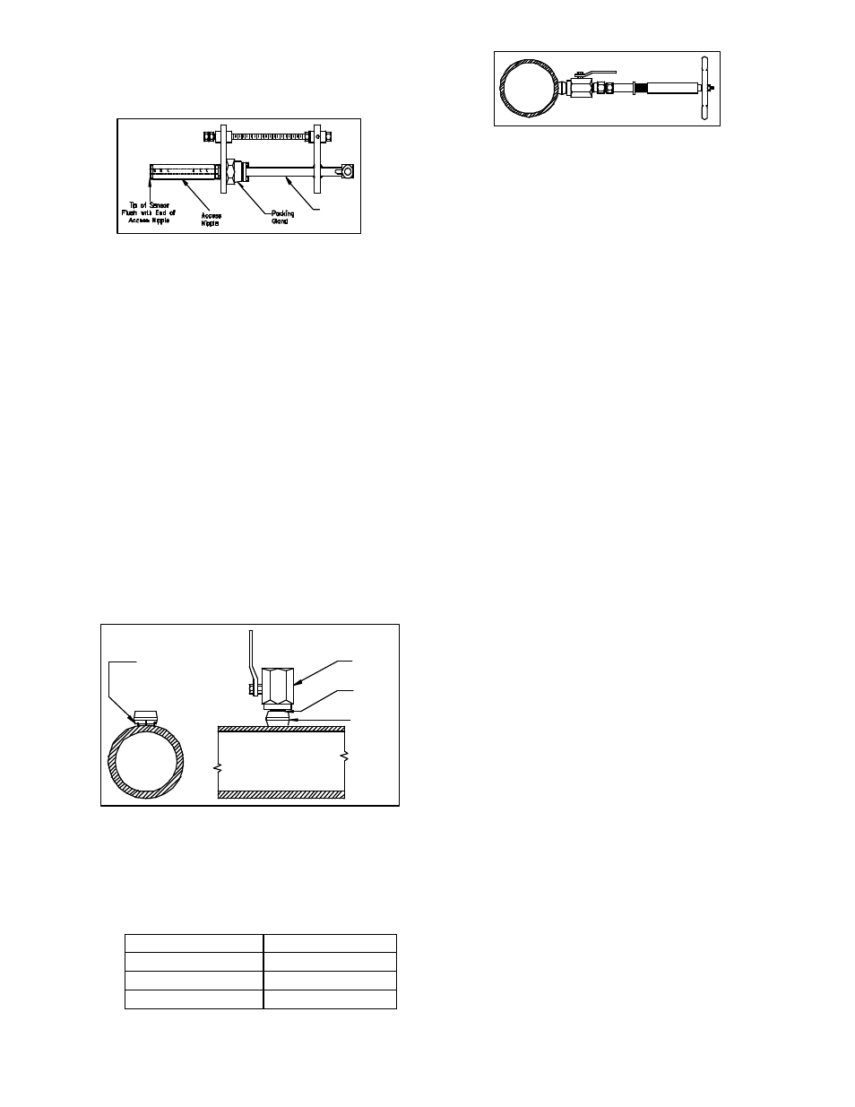
5.2
Install Access Nipple
Using proper sealant, thread access nipple into the
packing gland (Figure 3).
Figure 3. Access Nipple
5.3 Tighten Packing
Retract the Verabar such that the tip of the sensor is
flush with the end of the access nipple (Figure 3).
Tighten the three packing bolts on the packing gland.
5.4 Weld Threadolet to Pipe
Mark the location where the Verabar is to be mounted.
Position the threadolet over the center of the mark.
Using the appropriate weld gap, tack weld the threadolet
into position. Protect threads on the threadolet, then
finish welding the threadolet to the pipe per applicable
codes.
5.5 Install Close Nipple & Access Valve
Using the appropriate pipe thread sealant, install close
nipple and access valve. Orient the valve (Figure 4) such
that for horizontal pipes the valve handle is in-line
(perpendicular for vertical pipes) with the centerline of the
pipe. Be sure the valve handle does not hit the pipe
during opening and closing of the valve. Verify that the
close nipple and access valve are properly tightened,
because beyond this point, they will not be serviceable
without depressurizing the line.
Figure 4. Weld Gap
5.7
Drill Hole in Pipe
•
With the access valve in the full open position,
install an appropriate Hot Tap Drilling Machine
(Figure 5) and drill a hole in the pipe (hole sizes
per the chart below). Follow the instructions given
by the Hot Tap Drilling Machine.
Sensor Size
Hole Dia
V200-05
1/2" (13mm)
V200-10
1” (25mm)
V200-15
1-1/2” (38mm)
•
After the hole is completely drilled, retract the Hot
Tap Drilling Machine. Shut off the access valve
prior to removal of the Hot Tap Drilling Machine.
Figure 5. Hot
Tap Drilling
Machines
Note: There are numerous Hot Tap Drilling Machines on
the market with various pressure and temperature
ratings. These devices can usually be rented at a local
utility company. For more information concerning Hot
Tap Drilling Machines, the following companies can be
contacted: Mueller Co., Decatur, IL (217) 423-4471 or
T.D. Williamson Inc., Tulsa, OK (918) 446-1941.
5.8
Mount Sensor Assembly to Access
Valve
Apply appropriate thread sealant to the access nipple
and thread the access nipple into the access valve.
Orient the sensor such that the arrow labeled “flow” on
the instrument head is in the direction of the flow in the
pipe to within 3° (orientation per Figure 6).
5.9
Vent Access Valve to Verify No
Leaks are Present
With the instrument valves shut, slowly crack open the
access valve and verify that there are no process fluid
leaks. If leaks are present, shut off the access valve and
tighten the leaky joint.
5.10 Grease Drive Rod
•
High temperature grease has been applied to the
threaded rod(s) at the factory. Verify the threaded
rod is adequately greased prior to inserting the
sensor. If necessary, smear grease on the
threaded drive rod(s). Grease should also be
applied to the zerk fitting located on the threaded
bushing (Figure 7). A high temperature grease
should be used on all steam applications and for
temperatures above 200°.
•
Grease should be applied prior to subsequent
insertions and retractions.
5.11 Insert Verabar Sensor Assembly
Warning: The flow rate must be decreased to the
amount stated on the Verabar tag: the maximum
insertion/withdrawn DP/flow limit.
•
The Verabar should be oriented such that the
arrow on the head is pointing in the direction of
flow.
•
Completely open the access valve. Then, using
the drive nut, insert the sensor.
•
The tip of the sensor should completely bottom on
the sensor until firm resistance is met. This will
occur when the sensor plate is approximately 2”
(51mm) from the top of the packing gland.
•
Thread the jam nut toward the threaded bushing.
The jam nut should press tightly against the
threaded bushing. This will lock the drive rod in
place and maintain the sensor position in the pipe.
Cover
Tube
Gap (1/16" [1.5mm] typical
Tack Weld
Protect Threads
Complete Weld
Access
Valve
Close
Nipple
Threadolet