Velleman projects K8023 Assembly instructions User Manual
Page 9
9
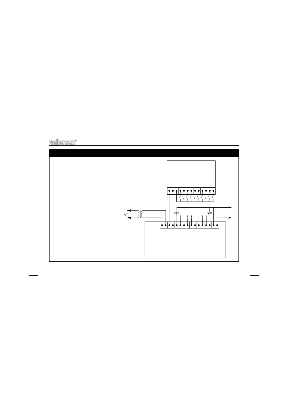
Connect both PCB’s P8023S and P8023R according to fig.1.
Both push buttons and switches can be used to control the
inputs. Keep the distance between the switches or push
buttons and the circuit as short as possible. If the circuit is
used in a noisy environment (e.g. proximity of electric motors,
transformers, ….) or if the distance between the switches and
the circuit exceeds 1m (3"), a shielded cable must be used to
connect the switches. The shield must be connected to the
‘COM’ terminal.
If the K8023 circuit is powered from
an AC source, then you will need an
external DC source to power the
relays, and the ‘+ Vext’ terminal must
be connected. (fig 1).
13. Hook - up & Testing
Hook-up & testing
P8023S
P8023R
+VTX- COM 1 2 3 4 5 6 7 8 9 10
S1 S2 S3 S4 S5 S6 S7 S8 S9 S10
RY1...............................................................RY10
+
-
V
ext
12V/300mA
12..15Vin +VTX- 1 2 3 4 5 6 7 8 9 10 +Vext GND
FIG. 1.0
- K7000 Assembly instructions (12 pages)
- K8042 Assembly instructions (12 pages)
- EDU10 Assembly instructions (24 pages)
- K2601 Assembly instructions (12 pages)
- K8039 Assembly instructions (20 pages)
- K8090 Assembly instructions (12 pages)
- K4305 Assembly instructions (14 pages)
- K8038 Assembly instructions (16 pages)
- K6714 Assembly instructions (16 pages)
- K8018B Assembly instructions (16 pages)
- K8050 Assembly instructions (20 pages)
- K8063 Infosheet (2 pages)
- VM152 Datasheet (1 page)
- K8006 Assembly instructions (16 pages)
- K8059 Infosheet (1 page)
- KA02 Datasheet (1 page)
- K2570 Assembly instructions (8 pages)
- K7102 Assembly instructions (12 pages)
- EDU08 Datasheet (1 page)
- K8092 Infosheet (1 page)
- K2543 Assembly instructions (12 pages)
- VMA03 Datasheet (1 page)
- MK179 Datasheet (1 page)
- K2579 Assembly instructions (12 pages)
- EDU05 (15 pages)
- K4040 Assembly instructions (28 pages)
- K7203 Assembly instructions (12 pages)
- K8027 Assembly instructions (12 pages)
- MK195 Datasheet (1 page)
- K8008 Assembly instructions (16 pages)
- K5600R Assembly instructions (14 pages)
- VM110N Datasheet (1 page)
- MK180 Datasheet (1 page)
- MK176 Datasheet (1 page)
- K7302 Assembly instructions (12 pages)
- MK190 Datasheet (1 page)
- VM179 Datasheet (1 page)
- K8049 Assembly instructions (12 pages)
- MK153 Assembly instructions (1 page)
- VM8095 Datasheet (1 page)
- VM134 Datasheet (1 page)
- K8077 Infosheet (1 page)
- K5201 Assembly instructions (16 pages)
- K8096 Assembly instructions (16 pages)