Velleman EDU01 User Manual
Page 31
www.vellemanprojects.com
Pag. 31
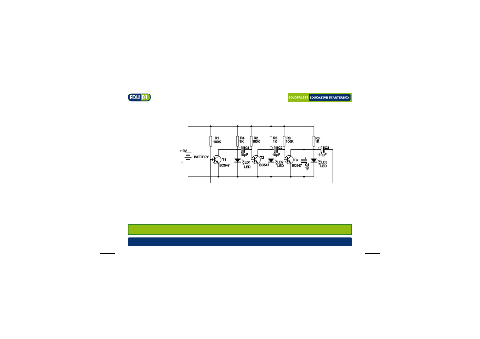
Required parts: 9V battery*, 3x1K resistor (brown black red gold), 3x100K resistor
(brown black yellow gold), 3 x red LED, 3x BC547 transistor, 3x10µF electrolytic capaci-
tor, 2x wire jumper
This circuit makes each LED light up shortly in succession. The circuit consists of 3 identical
channels. It is theoretically possible to expand; per LED a similar circuit is needed in series
with the previous. The capacitor of the next channel is charged when the transistor of the
previous channel is not conducting. As long as a certain transistor is not conducting, the rele-
vant LED will light up. Capacitor C4 is added to the circuit to create a certain starting condi-
tion when connecting power and to ensure a good operation.
Time to experiment: What happens when you change the value of R1, R2 and R3 to 10K?
- NC3MDL1-B (2 pages)
- NC3MXX (1 page)
- NC5FDL1 (2 pages)
- NC3MDL1 (2 pages)
- NC5MX (1 page)
- MK166 (1 page)
- К8095 (9 pages)
- VMa02 (4 pages)
- VM8090 (1 page)
- VM116 (32 pages)
- EDU02 (28 pages)
- VM202 (1 page)
- NL4MP (1 page)
- NC3MXX-BAG (1 page)
- VM120 (48 pages)
- VM153 EU (1 page)
- VM119 (32 pages)
- VM133 (24 pages)
- VM148 (24 pages)
- MK155 (1 page)
- VCC6 (20 pages)
- MK179 (2 pages)
- VMa04 (4 pages)
- VM122 (44 pages)
- VM134 (24 pages)
- NAC3FCA (1 page)
- VM121 (32 pages)
- К8048 (15 pages)
- К8048 (14 pages)
- VM150 (1 page)
- VMa01 (4 pages)
- NL4FX (2 pages)
- VM152 (20 pages)
- MK157 (1 page)
- VM112 (4 pages)
- VM130 (20 pages)
- NC3FXX-BAG (1 page)
- MK160 (1 page)
- NC5MDL1 (2 pages)
- VM118r (36 pages)
- VM179 (2 pages)
- VM192ir (2 pages)
- VM138 (40 pages)
- VM160 (20 pages)