Velleman EDU01 User Manual
Page 23
www.vellemanprojects.com
Pag. 23
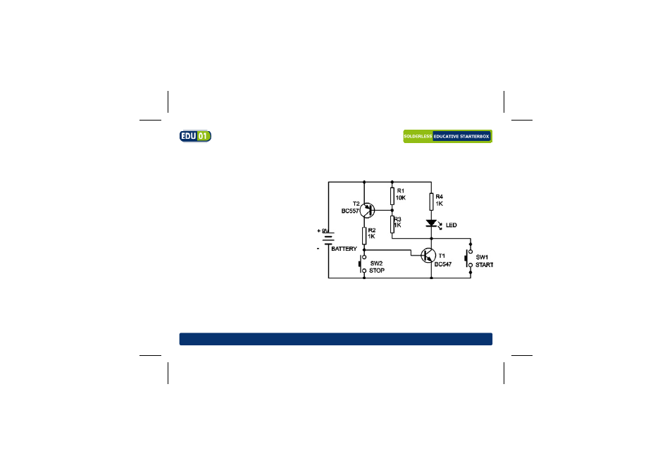
Required parts: 9V battery*, 3 x1K resistor (brown black red gold), 10K resistor
(brown black orange gold), red LED, 2 x push-button, 1x BC547 transistor, 1x BC557
transistor, 5 x wire jumper
How it works: The “START” button will
light up the LED; it will remain on when
the pushbutton is released. To switch off
the LED, press the “STOP” button.
T1 and T2 are in state of rest (OFF, no
current). By pressing the “START” but-
ton a current flows via R4 through the
LED. At the same time the base of T2 is
pulled low (was high via R1). Since the
value of R3 is much lower than R1 the
voltage on the base of T2 drops making
it conduct and via the collector of T2 and
R2. T1 also starts to conduct. From this point on, both transistors keep each other in con-
ducting state, even when the “START” button is released. Pressing the “STOP” button will
end the current flow towards the base of T1 and it will stop conducting. The circuit is inter-
rupted and T2 will also stop conducting. The LED will turn off.