Velleman EDU01 User Manual
Page 21
www.vellemanprojects.com
Pag. 21
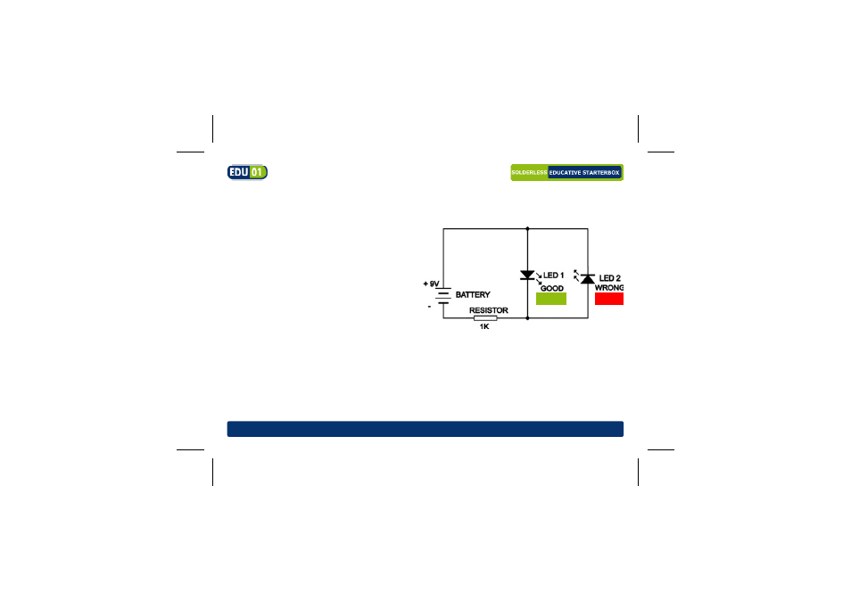
Required parts: 9V battery*, 1K resistor (brown black red gold), red LED, green LED,
wire jumper
How it works: When the 9V battery is
connected to the circuit with the right
polarity the green LED (good) will light
up. Current can flow from the "+" of the
battery through the green LED and via
the resistor back to the "–" of the battery.
The red LED (wrong) will not light up as it
is polarised in the opposite direction.
When swapping the connection of the
battery (switch the red and the black
wires) the red LED will light up. This way
we can determine whether a battery is
connected the right way or not.
GREEN
RED
See also other documents in the category Velleman Hardware:
- NC3MDL1-B (2 pages)
- NC3MXX (1 page)
- NC5FDL1 (2 pages)
- NC3MDL1 (2 pages)
- NC5MX (1 page)
- MK166 (1 page)
- К8095 (9 pages)
- VMa02 (4 pages)
- VM8090 (1 page)
- VM116 (32 pages)
- EDU02 (28 pages)
- VM202 (1 page)
- NL4MP (1 page)
- NC3MXX-BAG (1 page)
- VM120 (48 pages)
- VM153 EU (1 page)
- VM119 (32 pages)
- VM133 (24 pages)
- VM148 (24 pages)
- MK155 (1 page)
- VCC6 (20 pages)
- MK179 (2 pages)
- VMa04 (4 pages)
- VM122 (44 pages)
- VM134 (24 pages)
- NAC3FCA (1 page)
- VM121 (32 pages)
- К8048 (15 pages)
- К8048 (14 pages)
- VM150 (1 page)
- VMa01 (4 pages)
- NL4FX (2 pages)
- VM152 (20 pages)
- MK157 (1 page)
- VM112 (4 pages)
- VM130 (20 pages)
- NC3FXX-BAG (1 page)
- MK160 (1 page)
- NC5MDL1 (2 pages)
- VM118r (36 pages)
- VM179 (2 pages)
- VM192ir (2 pages)
- VM138 (40 pages)
- VM160 (20 pages)