Spicer Lubrication Specifications Universal Joints Tri-Fold User Manual
Page 2
Warning - Rotating shafts can be dangerous. You can snag clothes, skin, hair, hands,
etc. This can cause injury or death. Do not go under the vehicle when the engine is
running.
10 Series Driveshaft - Full Round Closed Yoke Holes
On 10 Series full round closed hole yokes, Figures B &C, loosen the bolts holding the bearing assembly
that doesn�t purge to release seal tension. It may be necessary to loosen the bearing assembly approximately
1/16 inch minimum. Apply grease gun pressure to purge seal or seals. If loosening does not cause purging,
remove the bearing assembly to determine cause of blockage.
Re-tighten or replace bolts based on bolt
designs as detailed in Chart 2 or 3.
10 Series Driveshaft - Serrated Bolt with Lock Patch (Full Round)
The self-locking design (Figure B) for full-round yokes uses serrated bolts with lock patch and DOES NOT require
a lock strap (as in Figure C). When re-installing this type, it is important that the old serrated bolt be replaced
and the new bolt torqued to the proper specifications.
Re-Installing Serrated Bolts: Loosely install new bolts. (See the following chart below for bolt part numbers.)
Tighten the new bolts to the torque specified in Chart 2. See Warning
Chart 3
Chart 2
Figure C
Figure B
Torque Specifications
10 Series Driveshaft - Bearing Plate Bolt Torque
Serrated Bolt Style
Non-Serrated Bolt Style
SERIES
BOLT P/N THREAD SIZE
BOLT TORQUE
(LB-FT)
(NM)
1610
5-73-109
.312-24
26-35
35-48
1710
6-73-109
.375-24
38-48
52-65
1760
6-73-109
.375-24
38-48
52-65
1810
6-73-109
.375-24
38-48
52-65
1880
7-73-115
.438-20
60-70
81-95
Warning - Failure to properly tighten bolts, and reuse of serrated bolts, could cause the driveshaft
to loosen and separate from the vehicle or machine, which could cause loss of control and could
result in serious personal injury or death.
Retightening of Bolts: Lock Strap Design. After lubricating the joint, run the bolts down until the bearing
plates are flush to the yoke faces, torque bolts to specification shown in Chart 3 and then bend the tabs of the
lock strap against the side of the bolt heads to lock the bolts in place. See Warning
Lack of proper lubrication is the most common cause of premature failure of universal joint kits and slip
assemblies. Properly sized Spicer U-joints that are adequately relubricated at recommended intervals will
normally meet or exceed fleet operational requirements. Inadequate relube cycles and failure to lubricate the
joints and slip spline properly not only cause joint failures, but lead to other problems such as slip spline seizures.
Proper relubrication flushes the U-joints and removes abrasive contaminants from the U-joint bearings.
Warning - Inadequate lubrication can cause driveline failure which can result in separation of the driveline
from the vehicle. A separated driveline can result in serious injury or death. In order to avoid driveline failure,
including driveline separation, you must:
1) Carefully review the lubrication specifications in this manual.
2) Be sure that you use only approved lubricants.
3) Be sure that you relubricate at recommended intervals.
Lubrication Procedure For Universal Joints
Spicer replacement universal joint kits contain only enough grease to provide needle bearing protection during
storage. It is therefore necessary to completely lubricate each journal cross and bearing assembly prior to
assembly into the driveshaft yokes. Each journal cross lube reservoir should be fully packed with a grease as
recommended in Chart 4. Each bearing assembly should also be wiped with the same grease, filling all the
cavities between the rollers and applying a liberal grease coating on the bottom of each bearing cap. After the kits
are installed into the driveshaft yokes and prior to placing into service, relube as follows:
1. Using the proper lubricant, purge all four bearing seals of each U-joint. This flushes abrasive contaminants from
each bearing and assures all four bearings are filled properly. *Purge the seals. Spicer seals are made to be purged.
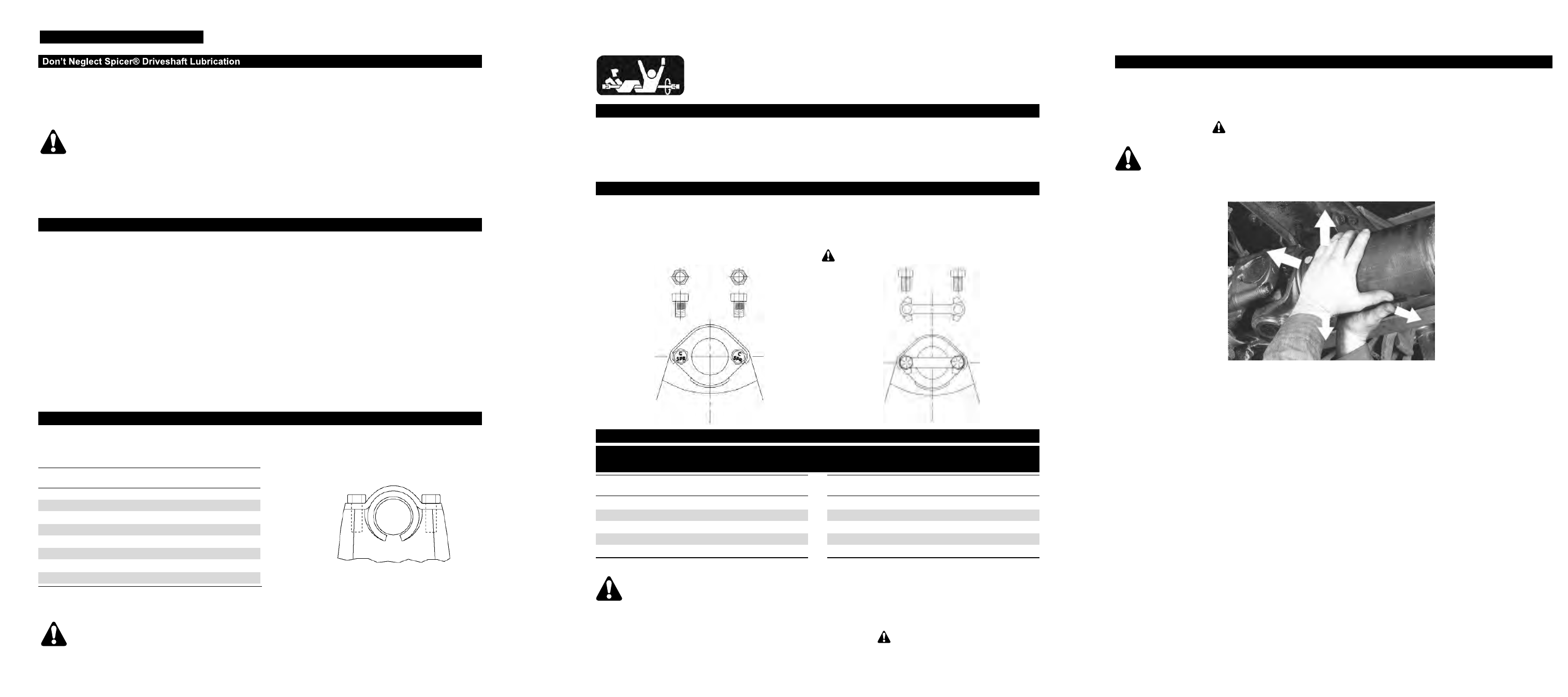
2. If any of the seals fail to purge, move the driveshaft from side to side while applying gun pressure. This allows
greater clearance on the thrust end of the bearing that is not purging (Photo 1).
3. Because of the superior sealing capability of the Spicer Seal design on the 1610, 1710, 1760, 1810, 1880,
SPL140, SPL170 and SPL250 Series, there will occasionally be one or more bearing seals of a U-joint that may
not purge. Release seal tension using the following seal tension release procedure:
*
Note: Purge - The point at which fresh lubricant has flowed from the seal.
Quick Disconnect (Half Round Yoke)
On Quick Disconnect“ half round end yokes , Figure A, remove the U-joint from the yoke, while insuring cup
will not disengage from u-joint cross, while grease gun pressure is being applied. Reinstall the U-joint Kit,
with
new bolts in the yoke, and torque to the specs shown in Chart 1.
SERIES BOLT P/N THREAD SIZE
BOLT TORQUE
(LB-FT)
(NM)
SPL90
6-73-412
.375-24
45-60
61-81
SPL140 5007417 M12x1.25-6g 115-125 156-169
SPL170 5007417 M12x1.25-6g 115-125 156-169
SPL250 5007417 M12x1.25-6g 115-125 156-169
1610
6-73-412
.375-24
45-60
61-81
1710
8-73-316
.500-20
115-135 156-183
1760
8-73-316
.500-20
115-135 156-183
1810
8-73-316
.500-20
115-135 156-183
Warning - Half round bearing strap retaining bolts should not be reused.
LUBRICATION SPECIFICATIONS
Figure A
Chart 1
SERIES BOLT P/N THREAD SIZE
BOLT TORQUE
(LB-FT)
(NM)
1610
5-73-709
.312-24
26-35
35-48
1710
6-73-209
.375-24
38-48
52-65
1760
6-73-209
.375-24
38-48
52-65
1810
6-73-209
.375-24
38-48
52-65
1880
7-73-315
.438-20
60-70
81-95
SPL Series Driveshaft
Apply grease gun pressure and purge all four bearings until fresh grease is seen at all four bearing seals.
1. If a bearing will not purge, apply pressure to yoke lug ear opposite of non-purging bearing while grease gun
pressure is being applied. This should firmly seat the ujoint against the cup seal and relieve seal tension of
nonpurging bearing. See
Warning, below. Repeat procedure for any other non purging bearings (See
Photo 1)
Warning - To prevent serous eye injury, always wear safety glasses when performing maintenance or
service. Failure to wear safety glasses could result in serious personal injury, and /or partial or complete vision loss.
Photo 1
2. If this procedure does not allow purging from targeted cups, attempt to relieve seal tension by one of the
following procedures:
For full round or inboard bearings, remove spring tab from non purging cup and apply pressure in opposing
direction to cup that will not purge to attempt to relieve seal pressure while grease gun pressure is being
applied.
For ß round or outboard bearings loosen bearing retainer from non-purging cup, insuring cup will not disengage
from u-joint cross, while grease gun pressure is being applied.
If all four bearings, purge fresh grease, replace removed spring tab and spring bolts and any loosened retainer
bolts with new. Follow procedure in service manual
3264-SPL for re-installation.
3. If the bearings still do not purge, complete removal of the universal joint kit is needed to determine cause of
blockage. See service manual
3264-SPL for proper removal procedure.