High Lifter Fender Kit for Polaris RZR 900 User Manual
High Lifter Hardware
High Lifter 2009-2010 Polaris RZR Floor Board Extension Kit
Note: This kit is not designed to fit or accommodate any year model of the Polaris Ranger XP or Crew!
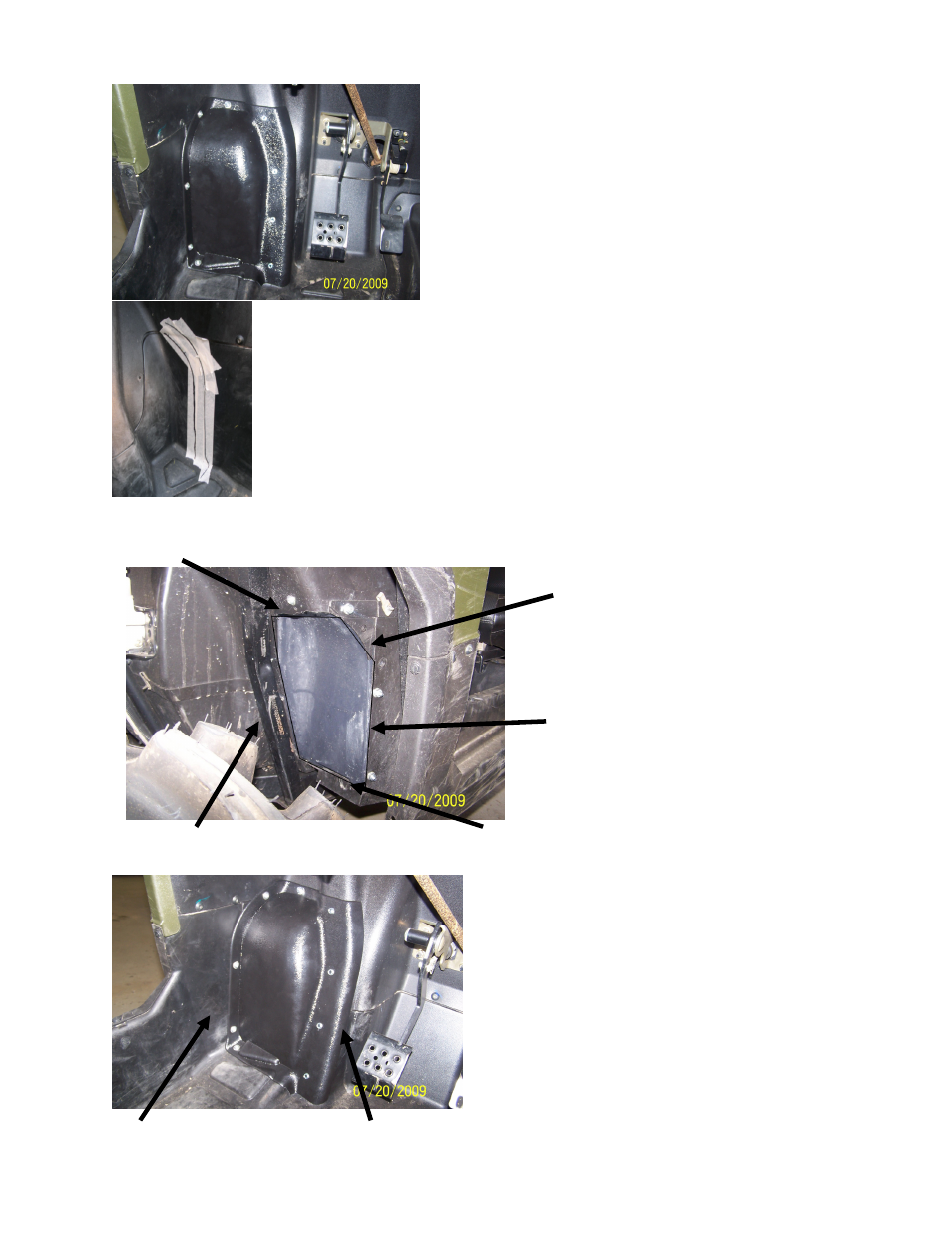
Step 1: Remove 2 factory screws and Tinnerman clips from
factory floor board at seam line of kick panel area. Place floor
extension in position in the vehicle. Press the floor kit firmly in
place and drill all pre-punched holes of the floor extension kit
using a 1/8” drill bit at factory metal floor support and 1/4” drill
bit in all remaining positions!. Using masking tape, outline the
floor extension panel and trace with a marker This will assist in
determining the area that will be removed from the factory floor
panel. Once drilling has been completed remove and set aside.
Note:
It is very important that the floor piece not move while
holes are being drilled! If needed secure panel with supplied-
screws while drilling holes!
Step 3: Using a plastic trimming tool and the below picture cut out the marked area and
remove and discard the removed factory floor board. Remove the tape. Note:
Take care
not to cut the tires or any other item that may be in the way of your cutting tool!
Suggested Plastic trimming tools: Dremmel or Dye grinder using a Taper Router bit no
larger than a 1/8” bit or an Air Saw can be used after a pilot hole for access has been
drilled or a Saws-All could be used.
Step 4: Once the floor pan has been cut out place the
new floor extension piece in place and using the 4 Phil-
lips modified truss screws, secure the floor piece to the
upright metal floor brace! Using a 1/4” drill bit re-drill
the remaining holes! (2 across the top and 3 down the
kick panel wall and 1 in the floor pan) Using the sup-
plied Button head bolts secure the floor kit to the kick
panel and floor board. The top 2 bolts should be passed
thru the drilled holes from the exterior to the interior, all
others will pass thru the holes from the interior to the
exterior of the vehicle.
Note:
It is very important that the bolt heads are
placed in the correct direction or damage may occur
to the tires if the bolts in the top section are not in-
stalled properly!
Repeat steps 1 thru 4 on the opposite side floor pan
area!
Trim along floor board metal brace!
Trim along floor panel seam line at upright bend of panel!
Do not trim beyond factory seam line where the upper
and lower factory floor panels meet!
Trim out excess kick panel
material, careful not to over
trim! Should be basically a
straight line
When trimming out this area use
the taped area as a guide for the
proper contour of this cut out!
Step 2: After completing step 1, add a second strip of masking tape to the inside diameter
of the outline taped area. Then draw approximately 1” inward from the original outline of
the floor extension. Proceed to step 3!
Phillips screws!
Button head bolts!
Hardware included: (10) Button head bolts, (20) Washers, (10) 1/4”
Nuts, (8) 1” Phillips screws.