High Lifter Dalton Pro Mudrunner Clutch Kit for Can-Am Outlander_Renegade 800 HO, 800 R (06-12) User Manual
Page 2
5)
BE CAREFUL when removing the belt, to leave the center hub sprage and spring retainer cup all the way IN on the
shaft.
NOTE DIRECTION OF BELT
(arrow) when you remove it. Make sure belt remains clean & free of any oils /
grease, a non-residue cleaner like brake cleaner maybe used to clean clutch surfaces, etc.
6) Remove the secondary pulley(rear clutch) by removing the center bolt. Be careful as you release the center bolt as the
spring in the rear clutch will push outwards when the bolt is off the threads. Have a helper hold the clutch inward
toward the vehicle while the bolt is removed.
7) When releasing the rear clutch to remove it TAKE NOTE of the position of the Helix Cam as the clutch comes
off. IMPORTANT that is goes in the correct position during re-assembly or the clutch could lock up at partial belt
travel and injury or damage may occur.
8) Install the supplied secondary spring and carefully re-install the rear pulley assembly taking note of the position of
the helix cam as you re install the secondary clutch.
9) Examine belt for inspection or replacment:( flat spots on edge from burning on take off, or holding brake etc)
-
CAREFULLY
install the belt around the rear clutch and center hub of the front clutch.
-
Make sure belt and clutch surfaces are CLEAN!
-
Note direction arrow
-
It maybe helpful to work the belt down into the rear pulley a bit to allow more slack on the belt. (Thread in the
bombardier “driven pulley expander” if available)
-
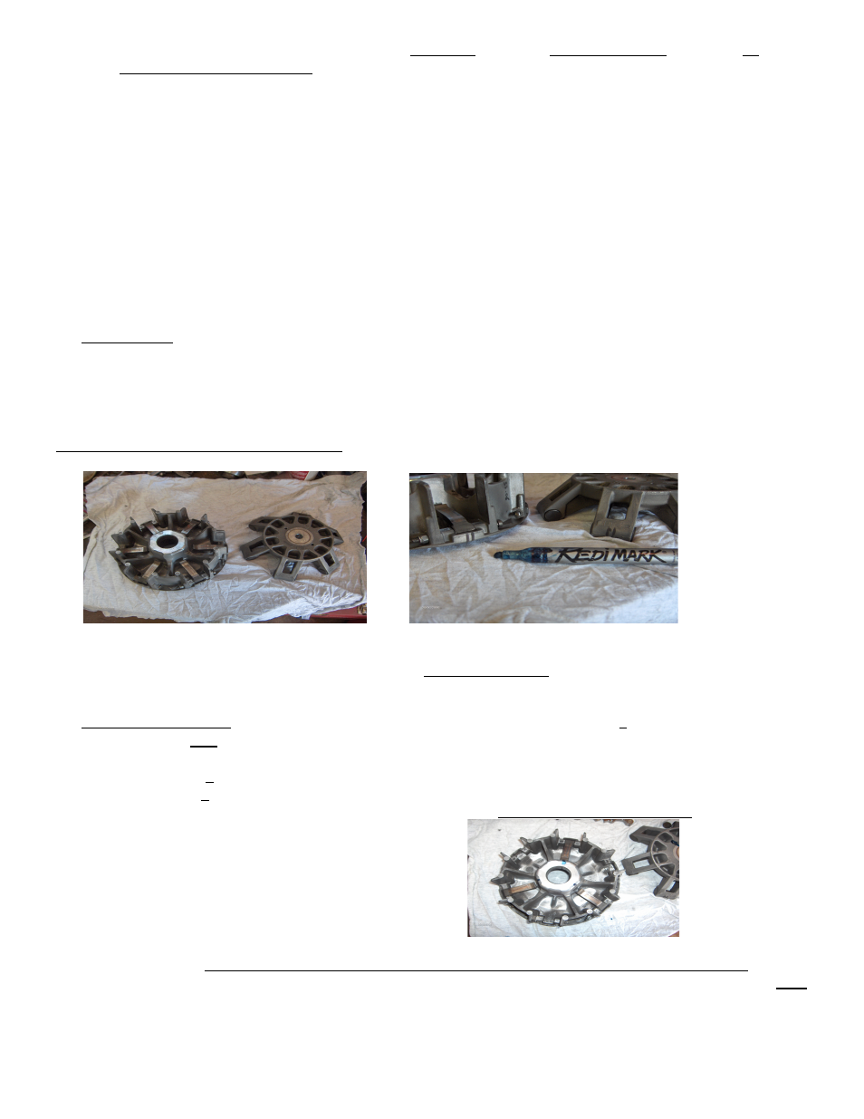
CHANGING PRIMARY COMPONENTS:
A) With the primary assembly still together, use a marker to show orientation of spider for re-assembly (Fig# 2&3)
B)
With the primary moveable assembly on the workbench (spring side down) carefully lift spider assembly out of the
moveable sheave.
ATTENTION: Be careful not to lose the plastic sliding buttons that will be exposed on the sides of each
finger of the spider, as you lift it out. Keep the spider flat and horizontal (as not to lose the plastic buttons) and sit it aside
gently. If any of these plastic slide buttons are damaged, replace them.
C)
VERY IMPORTANT:
The Bombardier / CAN-AM ATV drive clutch has places for 6 flyweights. On this 800cc
Outlander model all 6 positions are filled, and as many of you know (Bombardier service techs) there are other
models with only 3 or 4 of the positions filled and some are not used. Example: Outlander 400 has only 4
flyweights…. With 2 of the 6 positions empty (180 degrees opposite each other). In this case, we will be removing
and replacing only 3 of the flyweights and leaving 3 of the stock ones in tact. In fig #4 you can see that 3 of the stock
weights are still in the assembly and is ready for installation of the 3 Dalton adjustable flyweights.
The 3 stock and 3 adjustable weights are alternating. The 3 stock are 120 degrees apart, as are the 3 new ones. – Every
second one is replaced. THIS IS THE ONLY CONFIGURATION THAT 3 WEIGHTS CAN BE REPLACED.
It is well known in the snowmobile racing world, with 4 and 6 weight Drive clutches, that weights are often mixed. BUT,
it must be: a) evenly spaced (every second one or 120’ apart) or b) Directly opposite each other (180’ apart) with the
same weights.