Stage one instructions, Stage two instructions, Fig.b fig.a – High Lifter DynoJet Jet Kit for Yamaha YFZ 450 (04-05) User Manual
Page 2
STAGE ONE INSTRUCTIONS
Q427.001
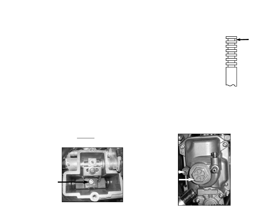
This is
Groove # 1
NOTE: This kit can be installed without completely removing the
carburetor.
1. Remove the top of the carb. Remove the allen screw (Fig.A) and pull
out the stock needle and spacers, noting order of assembly.
2. Install the Dynojet needle on groove #3 from the top. Install the small
Dynojet washer above the e-clip.
3. Remove the stock main jet. NOTE: The main jet can be accessed by
removing the nut from the bottom of the float bowl (Fig. B). Install the
Dynojet main jet adapter (DJA001) into the emulsion tube first. Install the
Dynojet main jet provided. If you are running the stock exhaust, install the
CJ130 for under 3000 ft. Install the CJ126 main jet from 3000-6000 ft.
Install the CJ124 main jet if above 6000 ft. If you are running an
aftermarket exhaust or slip-on with high flowing baffle, use the CJ134
main jet. Install the CJ130 main jet from 3000-6000 ft. Install the CJ126
main jet if above 6000 ft. Be sure that the jet you are changing is the
main jet.
4. Remove the stock pilot jet and replace with the Dynojet pilot jet
provided (DPJM048).
5.Locate the fuel mixture plug (Fig. B), if you see a screw head, proceed
to adjusting procedure. With the plug drill DD 5/32 provided, carefully drill
thru the plugs. NOTE: the mixture screw is directly underneath this plug,
be ready to pull back on the drill the instant you break through. Use the
screw provided to secure and remove the plug. Carefully turn the mixture
screw clockwise until lightly seated, then back out 1 turn.
Fig.B
Fig.A
NOTE: This kit can be installed without completely removing the
carburetor.
1. Remove the air box lid.
2. Remove the top of the carb. Remove the allen screw (Fig.A) and pull
out the stock needle and spacers, noting order of assembly.
3. Install the Dynojet needle on groove #3 from the top. Install the small
Dynojet washer above the e-clip.
4. Remove the stock main jet. NOTE: The main jet can be accessed by
removing the nut from the bottom of the float bowl (Fig. B). Install the
Dynojet main jet adapter (DJA001) into the emulsion tube first. Install the
Dynojet main jet provided. If you are running the stock exhaust, install the
CJ144 for under 3000 ft. Install the CJ140 main jet from 3000-6000 ft.
Install the CJ136 main jet if above 6000 ft. If you are running an
aftermarket exhaust or slip-on with high flowing baffle, use the CJ150
main jet. Install the CJ146 main jet from 3000-6000 ft. Install the CJ142
main jet if above 6000 ft. Be sure that the jet you are changing is the
main jet.
5. Remove the stock pilot jet and replace with the Dynojet pilot jet
provided (DPJM048).
6. Locate the fuel mixture plug (Fig. B), if you see a screw head, proceed
to adjusting procedure. With the plug drill DD 5/32 provided, carefully drill
thru the plugs. NOTE: the mixture screw is directly underneath this plug,
be ready to pull back on the drill the instant you break through. Use the
screw provided to secure and remove the plug. Carefully turn the mixture
screw clockwise until lightly seated, then back out 1 turn.
STAGE TWO INSTRUCTIONS
Remove this allen screw
to access the needle
Fuel mixture screw
plug.
Remove this nut to
access the main jet
and pilot jet.
NOTE:
1. If you remove the cone shaped screen from the air box you will need to use the CJ140 main jet with
Stage 1 and the CJ165 main jet with the Stage 2.
2. If you are using an aftermarket exhaust with a Quiet Baffle install the main jet that is for the stock exhaust.