Dunlop Manufacturing DB01 User Manual
Page 7
heel of the pedal, are hard wire connected together and are not
switched. This is like a signal pass through configuration, and the
jack on the left hand side can then be used as an input and the
adjacent jack (left jack closest to the toe of the pedal) as the output.
DUAL INDICATORS ON TAIL HOUSING
Located on the tail on the lower housing, there are two LED high
brightness indicators, a red and green: the red LED, when illuminat-
ed, indicates that the pedal has the boost switch on, which becomes
active when the effect is engaged; the green LED, when on, indi-
cates that the effect is on. These LED’s have been placed in this par-
ticular location for ease of visibility when approaching the effect.
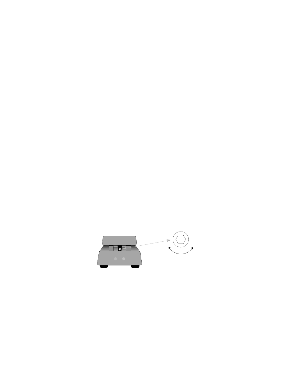
Adjustable Rocker Torque
This pedal comes with an adjustable torque clutch that allows the
user to control the amount of resistance the rocker has to being
moved. The adjustment is located under the rocker at the heel of
the pedal. By placing the rocker toe down and looking under the
rocker heel, you can see an adjustment allen head screw. By
turning this screw clockwise you can increase the rocker torque
and conversely, counterclockwise, decreases the rocker torque.
Adjustable Rocker Torque: Turn the allen
screw counter-clockwise to loosen the
pedal; clockwise to tighten.