Blue Ox BX88100 User Manual
Page 3
BX88100
Universal AutoStop™
Operation Manual & Installation Instructions
292-2215 Rev A
Page 3 of 12
10/30/13
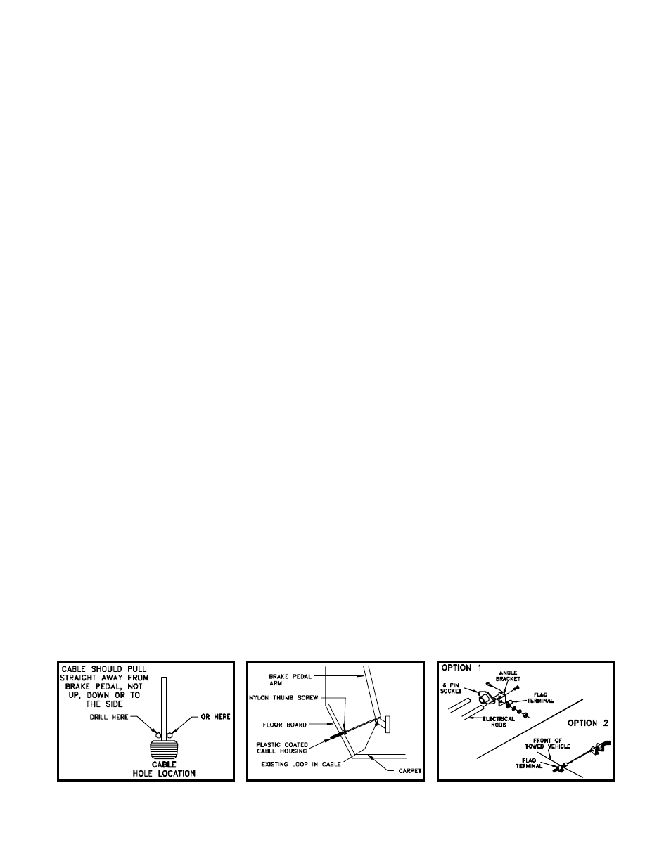
1. From the drivers seat note the distance and direction from the steering column to the brake pedal
when the brake pedal is fully depressed. This will normally be a little below and a little inboard of
the steering column. Mark the spot on the carpet with chalk where the cable should pass through
the floor. Measure the distance and direction and confirm that a drilled hole will not interfere with
anything fastened or close to the drilled hole. When selecting the location for the hole, it should be
positioned so the cable is pulling straight back on the brake pedal arm, not to either side and not
up or down. (Figure 3 & 4)
2. After you have confirmed that the location for the hole will not cause any problems, pull the carpet
back and drill a 1/8 inch pilot hole. Allow the drill bit to just barely break through the metal floor.
Next, inspect where the hole actually is from the engine compartment side to verify that this loca-
tion will not cause problems and to see how the cable aligns with the brake arm. If the hole needs
to be relocated, redrill and seal the previous hole with a rivet or sealant. When alignment is cor-
rect, enlarge the pilot hole with a 5/16 inch bit. Cut a slit in the carpet to correspond to the hole in
the floor.
3. Now you are ready to install the coated brake cable housing in the towed vehicle. Pull the inside
cable from the housing and set aside. The cable should run through the hole drilled in the floor
board into the engine compartment. Visually select a route that will not interfere with any moving
components or possibly contact electrical terminals. Route the cable to the central area (prefer-
ably through the opening where the attachment tabs extend through) of the front plastic facia. The
cable housing should be fastened in the engine compartment (on frame) with flag type terminals
provided in parts bag. Fasten the end of the plastic housing to the baseplate with the supplied
angle bracket. Figure 5 NOTE: Flag terminals are used so the cable housing is stationary allowing
the inside cable to move freely. When installed properly, the nylon thumb screw should be showing
on top of the carpet. Avoid abrupt bends in the cable housing as this will cause friction and prema-
ture wear of the cable. The cable housing should protrude a 1/2” beyond the bumper, or bumper
skirt or where ever the flag terminal is mounted, pointing directly at the hitch ball. Figure 5
4. Lubricate the cable with silicon spray and feed the cable back through the front end of the cable
housing into the passengers compartment. Loop the cable around the brake pedal arm allowing
the cable to feed directly and straight into the cable housing. If alignment is proper, the cable will
feed into the cable housing when the brake pedal is depressed. See Figure 4. Leave 1/2” of cable
housing extending from the flag terminal on the front of the vehicle. See Figure 5.
Figure 4
Figure 5
Figure 3
AutoStop™ Cable Attachment
continued to next page