Requirements – Blue Ox BX8894 User Manual
Page 12
REQUIREMENTS
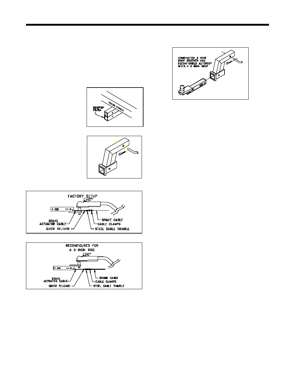
Combining the drop receiver and a rise in the
AutoStop will give a four (4) inch drop. (Figure 5)
B. You may use any conventional style tow bar with
the hitch ball at the towing vehicle. (No reversed
tow bars).
C. You must tow the vehicle with all four (4) wheels on
the ground.
D. The loaded weight of the towed vehicle must not
exceed the weight rating of any of the towing
accessory components such as; the tow bar, the
hitch ball, the receiver hitch, the receiver cross pin,
the safety chains, or the AutoStop.
NOTE: The AutoStop does not allow you to tow
more than the ratings of your towing hardware, it
just reduces the stopping distance of the
combination.
ILLUMINATED DASH INDICATOR LIGHT IN RV
WARNING:
Motorhome dash light must be installed
according to installation instructions or warranty
will be void.
A. RV DASH LIGHT
1. Dash light will allow a visual indication that the
towed vehicles' brakes are activated.
2. Should light remain "ON" after braking,
corrective action must be taken. "STOP" the RV to
investigate. You may be experiencing a
malfunction of the system, which would require you
to check, the braking system for proper operation.
a. Cable tension should comply with the
installation instructions.
b. Check wiring of relay in towed vehicle to
insure proper installation.
c. If breakaway device is installed, refer to its
installation instructions.
3. Should dash light activate while turning,
corrective action must be taken. "STOP" the RV to
investigate.
292-2215 7/02 1 of 10
REQUIREMENTS FOR PROPER OPERATION
A. You must have a two (2) inch square receiver type
hitch on your towing vehicle that aligns within two
(2) inches of the height of the tow bar.
NOTE: The tow bar may slope upward toward the
towing vehicle, but should not slope downward
toward the towing vehicle.
The AutoStop needs a level push on the ball
mount tube to operate properly. This requires that
the height of the
receiver tube be
adjusted rather than the
height of the ball as
happens normally.
There are several
options available if you
need to adjust the
receiver tube height.
A two (2) inch drop can
be achieved by welding
another receiver tube
under the existing
receiver tube. (Figure 1)
A six (6) inch drop
receiver is available that
pins into the existing
receiver. (Figure 2)
The AutoStop shown in Figure 3 is set up as it
comes from the factory.
The AutoStop can be reconfigured to give a three (3)
inch rise as shown in Figure 4.
NOTE: If this configuration is used, the internal parts
will need to be rotated so that the actuator cable
still protrudes from the lower driver’s corner of the
AutoStop. See Disassembly / Assembly
instructions Page 5-8.
Figure 2
Figure 5
Figure 3
Figure 4
Figure 1