Back view – Dell Latitude D430 User Manual
Page 11
Media Base Setup Guide
9
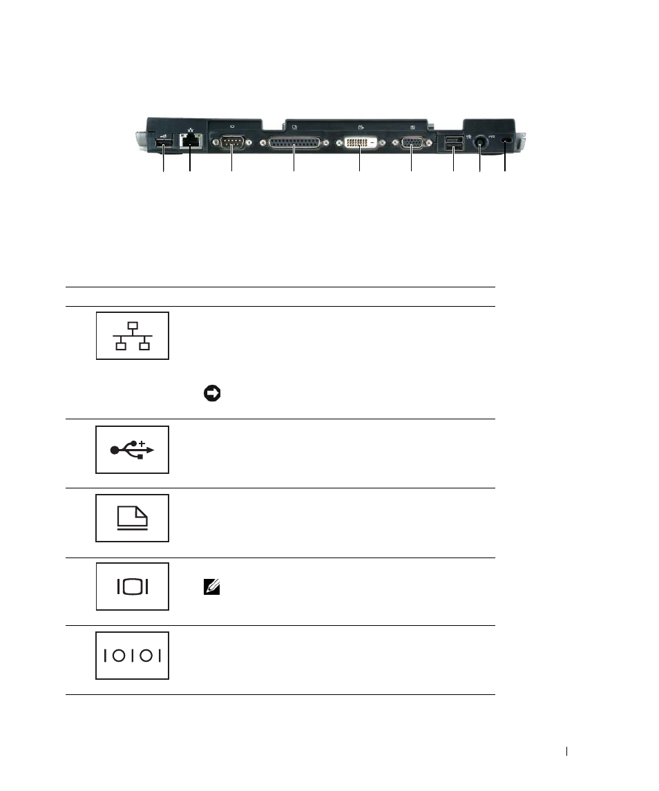
Back View
1
USB connector
2
network connector
3
serial connector
4
parallel connector
5
digital video connector (DVI) 6
VGA video connector
7
Powered USB connector
8
AC adapter connector
9
security slot
Connector
Description
N E T W O R K
C O N N E C T O R
—
Connects the media base to a
network. The two lights next to the connector indicate link
status and activity for a wired network connection.
For information on using the network adapter, see the
documentation that came with your computer.
NOTICE:
Do not plug a telephone cable into the network
connector.
U S B 2 . 0
C O N N E C T O R S
—
Connects up to four USB
2.0-compliant devices; including a powered USB.
P A R A L L E L
C O N N E C T O R
—
Connects a parallel device, such as a
parallel printer.
V I D E O
C O N N E C T O R
—
Connects an external VGA monitor.
NOTE:
When your computer is docked, use the video
connector on the media base.
S E R I A L
C O N N E C T O R
—
Connects a serial device, such as a
serial mouse or a handheld device.
1
2
3
4
5
6
8
7
9