Assembly – Bosch GLM 80 + R 60 Professional User Manual
Page 20
20 | English
2 609 141 088 | (7.8.13)
Bosch Power Tools
Product Features
The numbering of the product features shown refers to the il-
lustration of the measuring tool on the graphic page.
1 Display
2 Measuring button
3 Button for grade measurement / calibration **
4 Button for function mode / basic settings **
5 Minus button
6 Button for result / timer function **
7 Button for measured-value list / storage of constant **
8 Button for clearing the internal memory / On/Off **
9 Positioning pin
10 Button for selection of the reference level
11 Plus button
12 Button for length, area and volume measurement
13 Charge socket cover
14 Socket for charge connector
15 Fixture for carrying strap
16 Laser beam outlet
17 Reception lens
18 Serial number
19 1/4" thread
20 Laser warning label
21 Charge connector
22 Battery charger
23 Protective pouch
24 Measuring rail
25 Locking lever for measuring rail
26 Tripod*
27 Laser viewing glasses*
28 Laser target plate*
* The accessories illustrated or described are not included as
standard delivery.
** Keep button pressed to call up the extended functions.
Display Elements
a Measured-value lines
b “ERROR” indication
c Result line
d Digital vial / position of measured-value list entry
e Measured-value list indicator
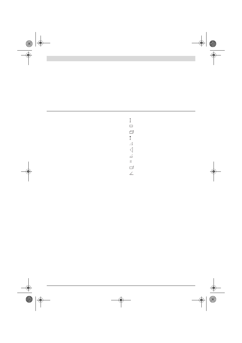
f Measuring functions
g Battery charge-control indicator
h Laser, switched on
i Measurement reference level
k Temperature warning
Assembly
Battery Charging
Do not use a different battery charger. The battery
charger provided is matched to the lithium ion battery in-
stalled in your measuring tool.
Observe the mains voltage! The voltage of the power
source must correspond with the data on the type plate of
the battery charger.
Note: The battery is supplied partially charged. To ensure full
capacity of the battery, completely charge the battery in the
battery charger before using your power tool for the first time.
The lithium ion battery can be charged at any time without re-
ducing its service life. Interrupting the charging procedure
does not damage the battery.
When the bottom segment of the battery charge-control indi-
cator g flashes, only a few more measurements can be carried
out. Charge the battery.
The charge procedure begins as soon as the mains plug of the
battery charger is plugged into the socket outlet and the
charge connector 21 is plugged into socket 14.
A) For measurements from the rear measuring-tool edge, 100 % reflectance of the target (e.g., a white-painted wall), weak backlight and 25
°C
oper-
ating temperature. Additionally, a deviation influence of
±
0.05 mm/m must be taken into account.
B) For measurements from the rear measuring-tool edge, 10 – 100 % reflectance of the target, strong backlight and – 10 °C to +50 °C operating tem-
perature. Additionally, a deviation influence of ±0.29 mm/m must be taken into account.
C) For measurements with the rear side of the unit as reference, the max. measuring range is ±60°
D) After calibration at 0 ° and 90 ° with an additional grade error of ±0.01 ° /degree to 45 ° (max.).
E) In the continuous measurement function, the maximum operating temperature is +40 °C.
F) at 25 °C
G) For a new and charged battery without display illumination and tone signal.
Please observe the article number on the type plate of your battery charger. The trade names of individual battery chargers may vary.
Please observe the article number on the type plate of your measuring tool. The trade names of the individual measuring tools may vary.
The measuring tool can be clearly identified with the serial number 18 on the type plate.
Length measurement
Area/surface measurement
Volume measurement
Continuous measurement
Indirect height measurement
Double indirect height measurement
Indirect length measurement
Timer Function
Wall-surface measurement
Grade Measurement
1
1
2
1
OBJ_BUCH-1347-005.book Page 20 Wednesday, August 7, 2013 4:12 PM