English – ASRock Z68 Extreme7 Gen3 User Manual
Page 43
43
ASRock Z68 Extreme7 Gen3 Motherboard
English
HDMI_SPDIF Header
HDMI_SPDIF header, providing
(2-pin HDMI_SPDIF1)
SPDIF audio output to HDMI
(see p.2 No. 37)
VGA card, allows the system to
connect HDMI Digital TV/
projector/LCD devices. Please
connect the HDMI_SPDIF
connector of HDMI VGA card to
this
header.
SPDIFOUT
GND
1
Serial port Header
This COM1 header supports a
(9-pin COM1)
serial port module.
(see p.2 No. 35)
IEEE 1394 Header
Besides one default IEEE 1394
(9-pin FRONT_1394)
port on the I/O panel, there
(see p.2 No. 32)
is one IEEE 1394 header
(FRONT_1394) on this
motherboard. This IEEE 1394
header can support one IEEE
1394
port.
+12V
GND
+12V
1
RXTPBM_0
GND
RXTPAM_0
RXTPBP_0
GND
RXTPAP_0
1
DATA
CLK
PWR(+5VSB)
GND
PS2 Header
PS2 header is used to connect
(5-pin PS2_1)
the 5-pin connector on the cable
(see p.2 No. 33)
of PS/2 Mouse/Keyboard +
USB 2.0 Bracket to support one
PS2 Mouse/Keyboard port.
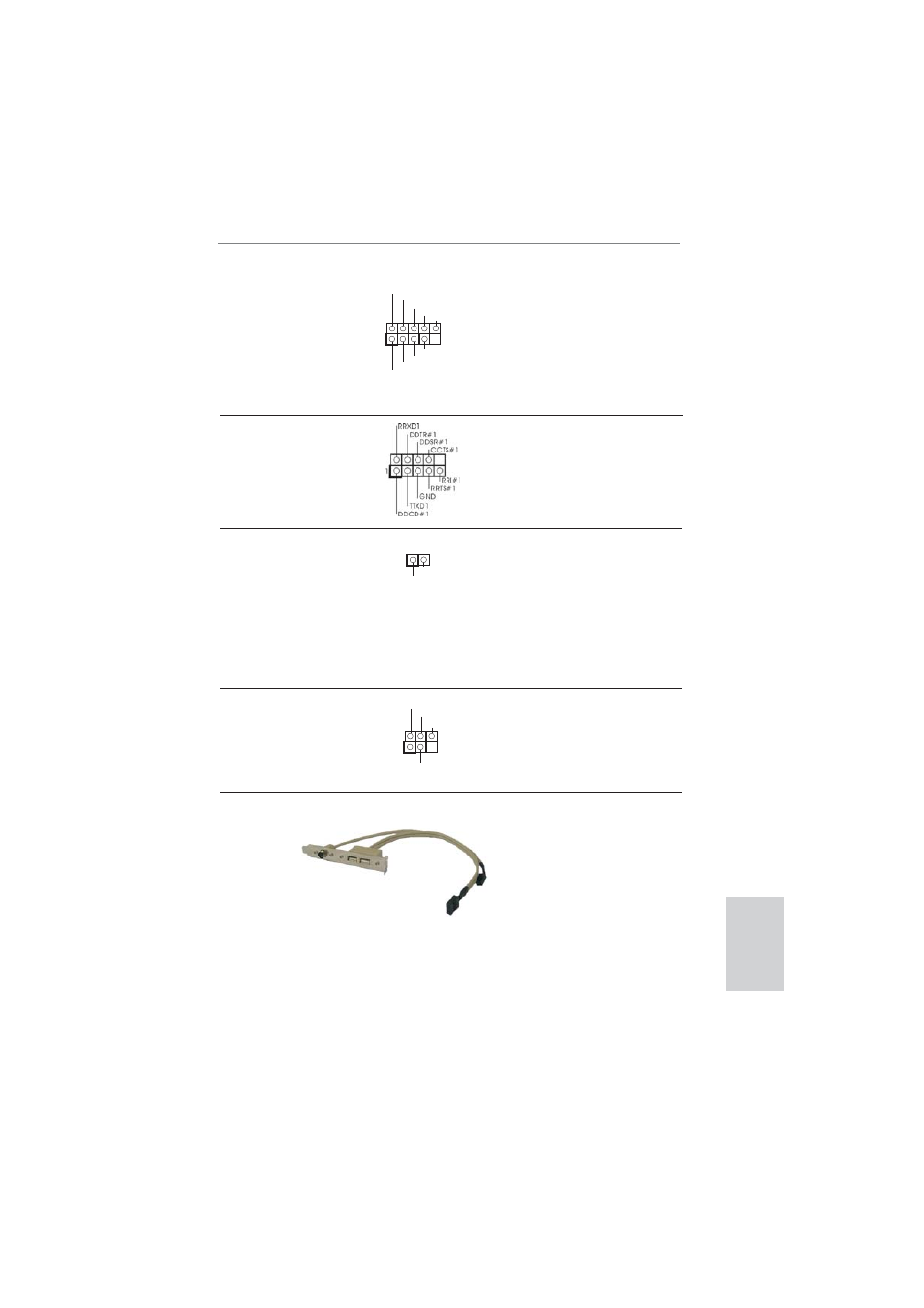
PS/2 Mouse/Keyboard + USB 2.0 Bracket
This PS/2 Mouse/Keyboard +
USB 2.0 Bracket can support
one PS2 Mouse/Keyboard port
and two additional USB 2.0
ports besides the I/O panel.
Please connect the 5-pin
connector on the bracket cable
to the PS2 header, and
connect the 9-pin connector on
the bracket cable to the USB 2.0
header (USB2_3, USB4_5,
USB6_7 or USB8_9) and fasten
the bracket to the chassis with
screws.