Ignition system test – "dwell" position, Fuel system tests – "dwell" position, Engine tests – "rpm" position – Actron Dwell__Volt Analyzer CP7605 User Manual
Page 5
8
9
scribed under DWELL/TACH/BREAKER POINT
RESISTANCE MEASUREMENTS
NOTE: When testing a vehicle with dual points,
alternately block one set of points open with a
piece of insulating material while the other set is
being tested.
5. Turn the ignition key ON. If the meter reads
voltage, (12.5 - 13.0) the points are OPEN. Crank
the engine a fraction of a revolution at a time
until the meter reads in the left hand area of
the scale.
The points are now closed.
Test Results:
Normal – Meter reads in the OK zone of the Points
scale. The Analyzer may indicate high point resis-
tance on a new set of points until they have been
run in the vehicle for a few miles and have been
properly seated. This condition may be ignored as
long as any defects discovered during the previous
visual check have been corrected.
Abnormal – If the meter indicates in the Bad zone
when the points are closed, the points may be
defective or the following faults may exist:
Poor distributor ground
Poor connection on the primary lead from
the distributor to the ignition coil
Defective distributor pigtail lead
Misaligned
points
Poor points/plate ground inside distributor
Correct the defect and repeat the test.
IGNITION SYSTEM TEST –
"DWELL" POSITION
DWELL TEST AND ADJUSTMENT – Breaker Point
Systems Only or Transistorized Systems which Use
Breaker Points.
1. Preparation:
Before performing the DWELL TEST AND
ADJUSTMENT PROCEDURE, read the vehicle
emission control label or the vehicle service
manual to determine what should be done with
the vacuum hoses connected to the distributor
and the various advance/retard solenoids. Most
often, the vacuum hose must be disconnected
from the distributor and the end plugged with
a plastic golf “tee” or other plug.
Connect the GREEN and BLACK clips as de-
scribed under TACH/DWELL/BREAKER POINT
RESISTANCE MEASUREMENTS.
2. Test
Procedure:
Start the engine and allow it to warm up (upper
radiator hose hot.)
Operate the engine at curb idle OR the RPM
specifi ed by the vehicle emission control label
or the vehicle service manual for measuring
dwell.
Check the RPM by switching the FUNCTION
SELECTOR TO RPM and reading the appropriate
meter scale. Return the FUNCTION SELECTOR to
DWELL and observe the correct dwell scale
NOTE: There is a direct relationship between dwell
and timing. However, it is only a one way relationship.
If you change the dwell angle of the breaker points,
you will automatically change the ignition timing.
Changing the timing, though, has no eff ect on the
dwell angle. FOR THIS REASON, IT IS IMPORTANT
TO RE-CHECK THE TIMING WHEN EVER THE DWELL
ANGLE HAS BEEN ADJUSTED.
DWELL ADJUSTMENT – Conventional Breaker Point
Systems
On GM distributors with a small metal slide cover,
lift the cover and insert a l/8" Allen wrench in the
adjusting screw socket and adjust the dwell by
turning the wrench, as shown in Figure 13.
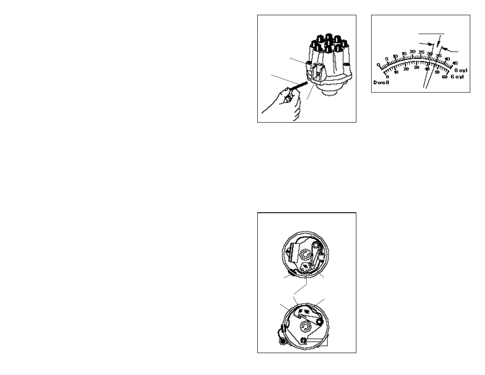
On Ford, Chrysler, American Motors, and other
distributors not equipped with a small metal ac-
cess slide cover, perform the following steps while
referring to Figure 14.
1. Remove coil wire from center tower of distributor
cap and ground the wire by connecting the loose
end to the engine or frame, See Figure 12.
2. Remove the distributor cap and rotor.
3. Connect a remote starter switch to the vehicle
or have an assistant crank the engine for you.
4. With ignition switch ON and engine cranking
observe reading on the Dwell scale.
5. To adjust Dwell, loosen the locking screw
slightly and adjust the point gap with a feeler
gauge according to the procedure outlined in
the vehicle service manual. After adjustment,
tighten locking screw, and recheck dwell while
cranking engine. Repeat procedure if necessary.
(Figure 14.)
6. Reassemble distributor and recheck dwell read-
ing with engine operating at idle speed. Repeat
steps 5 and 6 if necessary.
DWELL VARIATION TEST
Read the owner’s manual or engine compartment
decal and follow the instructions regarding vacuum
line or advance-retard solenoid connections when
Fig. 13
Typical General Motors
Breaker Points Distributor
WINDOW
ADJUSTMENT
SCREW
1/8" ALLEN
WRENCH
checking DWELL angle. Usually, the vacuum hose
must be disconnected from the distributor and
plugged
Increase the engine speed from idle to about
1500 RPM and note the dwell angle (Figure 15).
Return the engine speed to idle and again note
the dwell angle. If the diff erence between the two
dwell angle readings is more than 3 degrees, check
for excessive wear in the breaker point plate and
couplings or excessive wear in the distributor shaft
gear and bushings.
Fig. 14
Dwell Adjustment
(All, except Delco-Remy Sliding Window Distributors)
ADJUSTMENT
SLOTTED HOLE
BREAKER
POINTS
LOCKING SCREW
ADJUSTMENT
SCREW
BREAKER
POINTS
Fig. 15
Dwell
Variation
SECOND
READING
FIRST
READING
MORE THAN 3 DEGREES
FUEL SYSTEM TESTS –
"DWELL" POSITION
1. General Motors C-3 (Computer Command Con-
trol) Mixture Control Solenoid Dwell (Carbure-
tor equipped vehicles only). The GMC-3 system
controls Air/Fuel ratio with a mixture control
solenoid mounted in the carburetor. The basic
system performance check of this system calls
for the checking of the duty cycle or dwell of
the M/C solenoid. Note that regardless of the
number of cylinders in the vehicle, the reading
is always taken from the 6 cylinder scale.
2. This analyzer may be used to check C-3 Dwell
(duty cycle). Refer to your vehicle service
manual for hookup instructions and perfor-
mance results. See Figure 11.
ENGINE TESTS –
"RPM" POSITION
1. Carburetor Adjustments – There are several
adjustments which should be checked as part
of a performance tune-up. Those which require
engine RPM monitoring are:
a. Curb idle
b. Base idle
c. Solenoid Controlled idle
d. Fast idle
Your vehicle will likely have some combination
of these adjustments. Proper adjustment of
these settings is a requirement for good engine
performance and driveability.
2. Fuel Injection Adjustments – Some fuel injec-
tion systems have a minimum and maximum
authority adjustment which should be checked
during routine performance tune-up or when-
ever idle problems are encountered.
3. Miscellaneous Engine Test – Many of the test