Ignition system test – "volts" position – Actron Dwell__Volt Analyzer CP7605 User Manual
Page 4
6
7
GREEN
CLIP
GREEN
CLIP
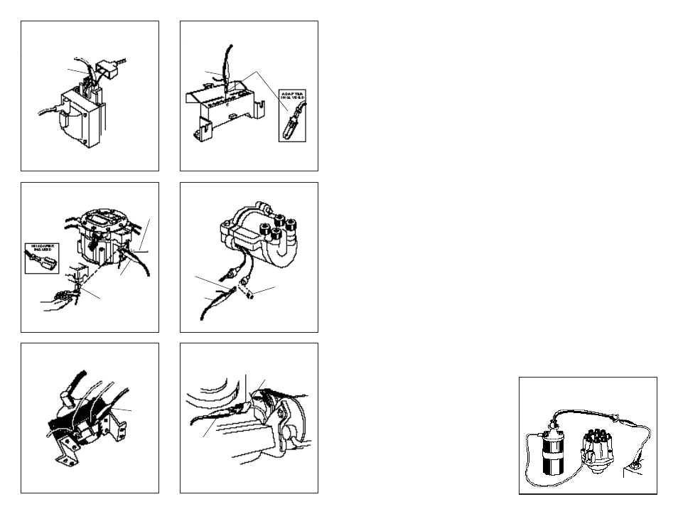
Fig. 8
Primary Tach Connection —
GREEN
Clip
Fig. 7
Primary Tach Connection —
GREEN
Clip
Fig. 6
Primary Tach Connection —
GREEN
Clip
Ford TFI Systems 1981 - 1986
Delco HEI 1974 - 1986 External Coil
INSERT
DIAGNOSTIC
ADAPTER
Fig. 9
Primary Tach Connection —
GREEN
Clip
Fig. 10
Primary Tach Connection —
GREEN Clip
GM Diagnostic Connector and
Delco HEI Systems 1976 - 1982
Toyota IIA (Integrated Ignition As-
sembly) 1983 - 1986
GREEN
CLIP
SPADE
TERMINAL
ADAPTER
GREEN
CLIP
REMOVE CAP
FROM TACH
TEST CONNEC-
TOR
GREEN
CLIP
ADAPTER
TO
IGNITION
SWITCH
Delco HEI 1974 - 1986 Integral Coil
Fig. 11
Performance Check ONLY
Note: This is NOT a Tach Connection point.
GM C3 (Computer Command Control)
GREEN CLIP or
Ground Jumper
– See Vehicle
Service Manual
DWELL CONNEC-
TOR (GREEN)
BASIC SYSTEM CHECK – Charging Voltage
1. GREEN CLIP – Connect to the Positive (+) Battery
terminal.
2. BLACK CLIP – Connect to Vehicle Ground.
3. FUNCTION SELECTOR – Volts
4. Start engine and allow it to warm up completely.
Operate it at curb idle.
5. With all accessories off observe the 16 volt scale
on the analyzer.
6. Normal Result – 13.2 to 15.2 volts or as specifi ed
in the vehicle service manual.
7. FUNCTION SELECTOR – RPM
8. Select a step on the fast idle cam which will
maintain engine speed between l800 and 2000
RPM (or have an assistant hold engine speed
in this range) through Step 12.
9. FUNCTION
SELECTOR
–
Volts
10. Observe the 16 volt scale on the analyzer. The
voltage should not have changed from Step 6
more than about .5 volts.
11. Load the electrical system by turning on the
lights, Hi fan, and wipers.
12. Observe the 16 volt scale on the analyzer. The
voltage should not drop below about 13.0
volts.
13. Shut off all accessories, return the engine to
curb idle, and shut it off . If the results obtained
in Step 6, 10 or 12 are signifi cantly diff erent
from those shown or from the vehicle service
manual values, further diagnosis is required:
see your vehicle service manual.
CRANKING VOLTAGE AND BATTERY CONDITION
If the engine cranks slowly or not at all, the battery,
cranking motor, and associated wiring may be
at fault. Check the cranking voltage as indicated
below.
1. Connect the analyzer to the vehicle battery as
shown in Figure 1.
2. Disable the engine from starting as shown in
Figure 12 or as explained in your vehicle service
manual
3. FUNCTION
SELECTOR
–
Volts
4. Crank the engine while observing the 16 volt
scale on the analyzer.
5. Normal Result – 9.6 volts or more at 70°F. Voltage
will drop slightly as temperature decreases.
6. If the results are signifi cantly out of specifi cation
consult your vehicle service manual for further
ENGINE GROUND
Fig. 12 Disabling Procedure
Breaker Point Ignition System
diagnosis.
7. If battery voltage remains abnormally high
(above approximately 10.5 volts) on a slow
or no cranking engine, the problem may be
loose or corroded connection(s) in the cranking
circuit.
MISCELLANEOUS VOLTAGE TESTS
This instrument can perform many of the voltage
tests called out in the vehicle service manual, such
as voltages at lamp sockets, motors, solenoids
and relays.
NOTE: The voltmeter function of this instrument can
be used anywhere the vehicle service manual calls
for voltage measurement except in those applica-
tions which call for 10 Megohm input impedance
or a digital voltmeter.
IGNITION SYSTEM TEST –
"VOLTS" POSITION
BREAKER POINT RESISTANCE TEST (Breaker Point
Systems Only)
1. Visually check the breaker points and associ-
ated wiring and connections. Check to see that
the lead from the distributor to the Negative
(-) terminal of the ignition coil is not damaged
(nicked insulation, etc.)
2. Remove the distributor cap and inspect the
breaker points. Properly adjusted breaker
points become light gray in color in normal
use. If they are blued, blackened or pitted, they
have exceeded their normal life.
3. To prevent the engine from starting, disable
the ignition system by grounding the coil tower
wire as shown in Figure 12.
4. Connect the GREEN and BLACK clips as de-