Functions, connections and accessories, Electrical system tests – "volts" position – Actron Dwell__Volt Analyzer CP7605 User Manual
Page 3
4
5
FUNCTIONS, CONNECTIONS AND ACCESSORIES
DESCRIPTION
The Model CP7605 Dwell/Tach/Voltmeter has a
clearly labeled function switch and meter as shown
in the Master Hookup diagram, Figure 1 below.
1. METER
This meter displays the following scales:
• Volts
0-16
• RPM
0-2000 (8 cylinder)
0-4000 (4 cylinder
– multiply
8 cylinder scale
by 2)
• RPM
0-2500 (6 cylinder)
• Dwell
0-45 degrees (8 cylinder)
0-90 degrees (4
cylinder–
multiply 8 cylinder by 2)
• Dwell 0-60 degrees (6 cylinder)
•
Points OK/Defective
2. FUNCTION
SELECTOR
This selects the RPM, Dwell, or Volts functions
of the instrument.
3. TEST
LEAD
Hook this lead to the proper test point in the
vehicle to perform tests as required and as
described below:
VOLTAGE
MEASUREMENTS
GREEN CLIP – Connect to the Positive (+) volt-
age source to be measured. (+ Battery terminal,
alternator output terminal, lamp socket, etc.).
BLACK CLIP – Vehicle ground.
CAUTION!
Avoid connecting the BLACK CLIP to the
negative(-) battery terminal or any fuel sys-
tem components in the event that glasses are
present which could explode from sparking
connections.
DWELL/TACH/BREAKER
POINT
RESISTANCE
MEASUREMENT
GREEN CLIP – Connect to the Tach or negative
(-) ignition coil terminal. See Figures 3 through
10 for specifi c applications
BLACK CLIP – Vehicle Ground. See CAUTION
under voltage measurements.
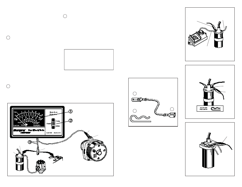
Fig. 1
Master Hookup Diagram
DISTRIBUTOR
DIST. OR
TACH
BAT.
GREEN
ENGINE
GROUND
BLACK
ACCESSORIES
See Figure 2.
1. GM DIAGNOSTIC ADAPTOR
The GM Diagnostic Adaptor is used to make
connection to vehicle equipped with the GM Di-
agnostic Connector, (1976 –1982). It is also used
to make connection to Toyota vehicles which
use the IIA (Integrated Ignition Assembly). See
Figures 9 and 10 for adaptor application.
2. GM HEI ADAPTOR
The GM HEI Adaptor is used to provide connec-
tion to the “TACH” terminal on GM HEI systems.
See Figure 7 for typical installation.
3. FORD COIL CLIP
The Ford Coil Clip is used for ignition systems
which have booted ignition coil connections.
See Figure 4 for clip application.
ELECTRICAL SYSTEM TESTS –
"VOLTS" POSITION
Fig. 2
Accessories
3
2
1
Fig. 3
Primary Tach Connection —
GREEN
Clip
Fig. 4
Primary Tach/Dwell Connection –
GREEN
Clip
Fig. 5
Primary Tach Connection —
GREEN
Clip
COIL
(BAT.)
GREEN
CLIP
TO BAL-
LAST
TO IGNITION
SWITCH
FORD
ADAPTER
TO DIST.
GREEN
CLIP
CONTROL
UNIT
TO CONTROL
UNIT
1974 Ford Electronic and All Breaker
Points Ignition Systems
All Chrysler Corporation Electronic Igni-
tions, 6 & 8 cylinder shown
1972 - 1986
GREEN
CLIP
Ford Solid State & Dura Spark systems
1975 - 1986
COIL