Actron GM Code Scanner CP9001 User Manual
Page 42
42
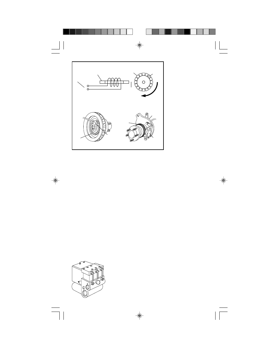
wheel). The ring is attached to the
wheel, drive axle or transmission shaft.
Whenever a tooth from the ring passes
by the sensor, it attracts the magnetic
field lines surrounding the magnet. As
the field lines move, they pass through
the wire coil and generate a small
voltage pulse (magnetic induction
principle). Thus, a voltage pulse is
generated every time a tooth passes
by the sensor coil. This voltage signal
is sent to the ABS computer.
The ABS computer determines wheel
speed by measuring how fast pulses
appear. The faster the wheel spins, the
more quickly pulses will appear. Note:
The voltage pulses get larger as the
wheel speeds up. (The computer
ignores pulse size.) Values can range
from a fraction of a volt (low speed) to
several volts (high speed).
Hydraulic Control Modulator
This is an assembly containing
solenoid operated hydraulic valves. It
is usually mounted
close to the master
cylinder. (Some
systems combine the
hydraulic control
modulator and the
master cylinder into
one complete unit.)
The valves are
connected in the brake
lines between the
master cylinder and
the wheel caliper (or
wheel cylinder). The
ABS computer controls
brake line pressure by
operating one, or
more, of these
solenoid valves. (In
ABS systems, the
process of varying
brake pressure is
called “modulation.”
This is why the solenoid assembly is
called a “modulator.”)
Some modulator types use two
solenoid valves per brake circuit: an
“isolation” valve and a “dump” valve.
Other types use a special “two-stage”
solenoid per brake circuit. This “two
stage” solenoid provides the same
brake fluid control as the “isolation”
and “dump” solenoids.
The “isolation” and “dump” solenoids
have two positions: coil off and coil
fully energized. The “two stage”
solenoid has an additional position:
coil off, coil
partially energized and coil
fully energized. ABS computers
controlling “two stage” type solenoids
have special built-in switching circuits
to energize the solenoid properly.
Refer to “How ABS Controls Brakes”
(later in this section) for a description
of how the modulator is used.
Accumulator and Electric Pump
These two components work together.
Depending upon system, their use (and
construction) will differ a great deal.
• Low Pressure type: Accumulator
and pump only used during ABS
operation.
– Accumulator acts as a reservoir. It
collects hydraulic fluid “bled” from
S
N
{
Wheel Speed Sensor Operation
To
computer
Magnet
Wire Coil
Air
gap
Teeth
Sensor
ring
Rotation
Wheel
speed
sensor
Sensor
ring
Hub and rotor
assembly
Sensor
ring
Axle
housing
Wheel
speed
sensor
Typical Front Sensor
Typical Rear Sensor
Hydraulic Control
Modulator
(Typical)