Abs basics, Typical 4-wheel anti-lock brake system, A general description of abs systems – Actron GM Code Scanner CP9001 User Manual
Page 40
40
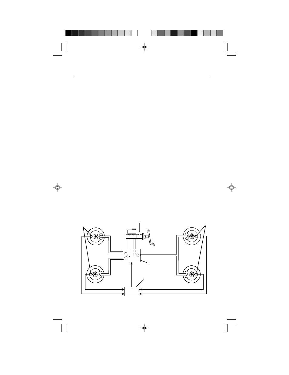
Typical 4-Wheel Anti-Lock Brake System
Courtesy of General Motors Corp.
Front Wheel
Speed Sensors
Electronic Brake
Control Unit
(ABS computer)
Rear Wheel
Speed Sensors
Hydraulic
Control
Modulator
Master Cylinder
ABS BASICS
A General Description of ABS Systems
The following is an overview of Anti-
Lock Brake Systems (ABS). There are
several different types and versions.
Refer to vehicle service manual for
specific details.
IMPORTANT: To service ABS systems
safely and effectively, you must obtain
a service manual for your vehicle and
carefully follow all procedures.
What is ABS?
ABS is a safety feature designed to
minimize accidents during braking.
When engaged, ABS stops the vehicle
in the shortest distance possible while
giving the driver the greatest amount
of steering control.
Heavy braking on non-ABS vehicles
often causes wheels to lock up. This
leads to a wheel skid condition
resulting in loss of maneuverability and
a long stopping distance. The job of
ABS is to prevent wheel lock-up.
The ABS System
An ABS system combines a conven-
tional hydraulic braking system along
with additional components including:
– An ABS computer (separate from
the engine computer)
– Wheel speed sensors
– Hydraulic control unit
The computer module controls the
ABS system. This module is called
Electronic Brake Control Module
(EBCM), or similar. The computer
monitors wheel speed, acceleration
and deceleration using signals sent by
the wheel speed sensors. If the
computer determines wheel lock-up is
likely during braking, it will control
brake pressure using the Hydraulic
Control Modulator. ABS components
and braking operation will be detailed
later in this section. As a safety
feature, the system reverts to normal
hydraulic braking operation if the ABS
computer cannot operate.