Usb interface, Communication parameters, Endpoints – ACS ACR100I SIMFlash II User Manual
Page 8: Smart card reader, Mass storage
Document Title Here
Document Title Here
Document Title Here
ACR100I Reference Manual
Version 1.00
Page 8 of 20
www.acs.com
.hk
www.acs.com.hk
6.0. USB Interface
The connection of the ACR100I to a computer through a USB port follows a USB Standard.
6.1. Communication Parameters
The ACR100I is connected to a computer through USB as specified in the USB Specification 2.0. The
ACR100I is working in high-speed mode, i.e. 480 Mbps.
6.2. Endpoints
The ACR100I uses the following endpoints to communicate with the host computer
6.2.1.
Smart Card Reader
6.2.2.
Mass Storage
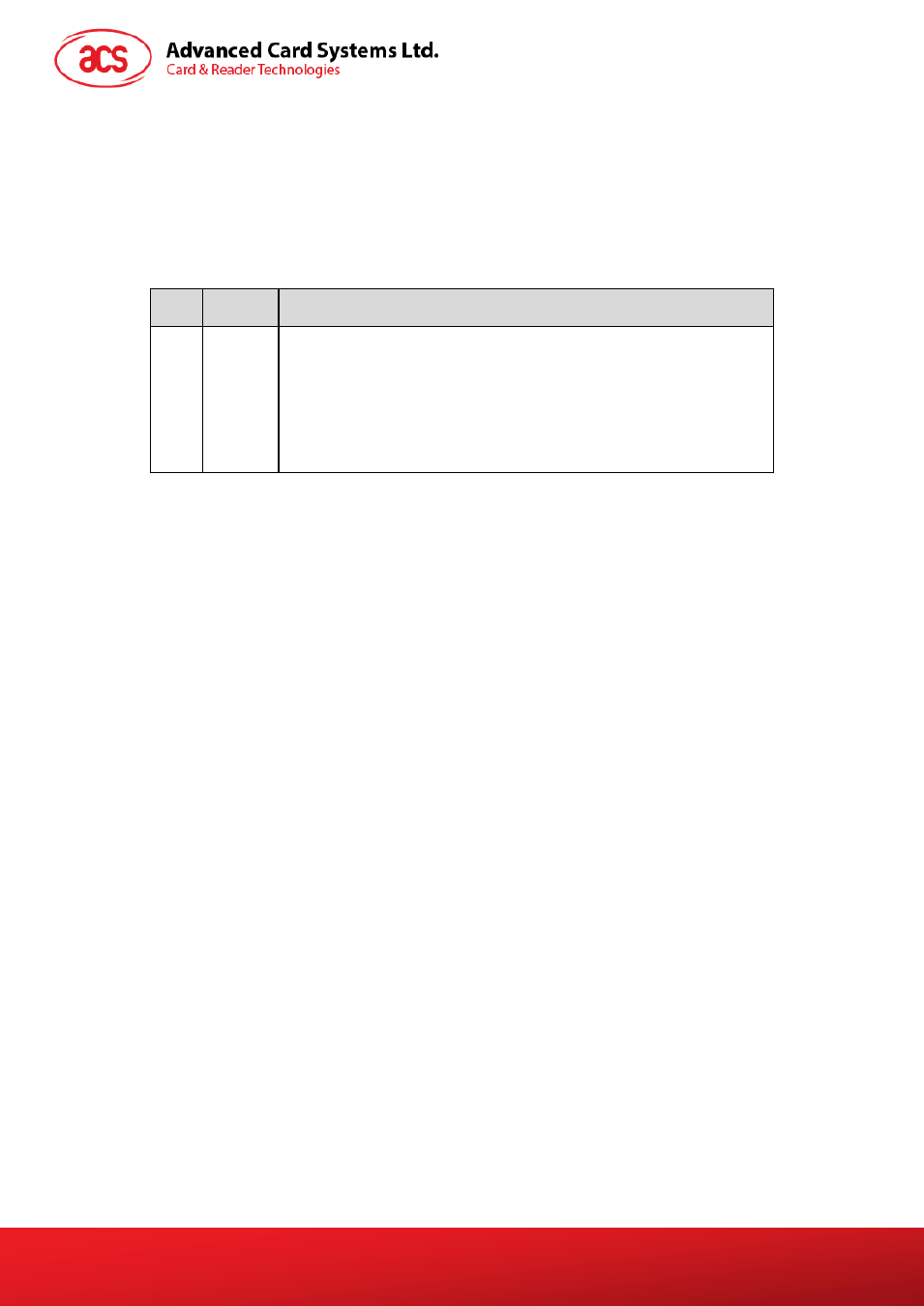
Control
Endpoint
For setup and control purpose
Bulk OUT
For command to sent from host to Device (data packet size is 512 bytes)
Bulk IN
For response to sent from Device to host (data packet size is 512 bytes)
Pin
Signal
Function
1
V
BUS
+5 V power supply for the reader (Max 500 mA, Normal 300 mA)
2
D-
Differential signal transmits data between ACR100I and PC.
3
D+
Differential signal transmits data between ACR100I and PC.
4
GND
Reference voltage level for power supply
Control
Endpoint
For setup and control purpose
Bulk OUT
For command to sent from host to ACR100I (data packet size is 64 bytes)
Bulk IN
For response to sent from ACR100I to host (data packet size is 64 bytes)
Interrupt IN
For card status message to sent from ACR100I to host (data packet size
is 8 bytes)