Pc_to_rdr_setparameters – ACS ACR100I SIMFlash II User Manual
Page 13
Document Title Here
Document Title Here
Document Title Here
ACR100I Reference Manual
Version 1.00
Page 13 of 20
www.acs.com
.hk
www.acs.com.hk
7.1.1.7.
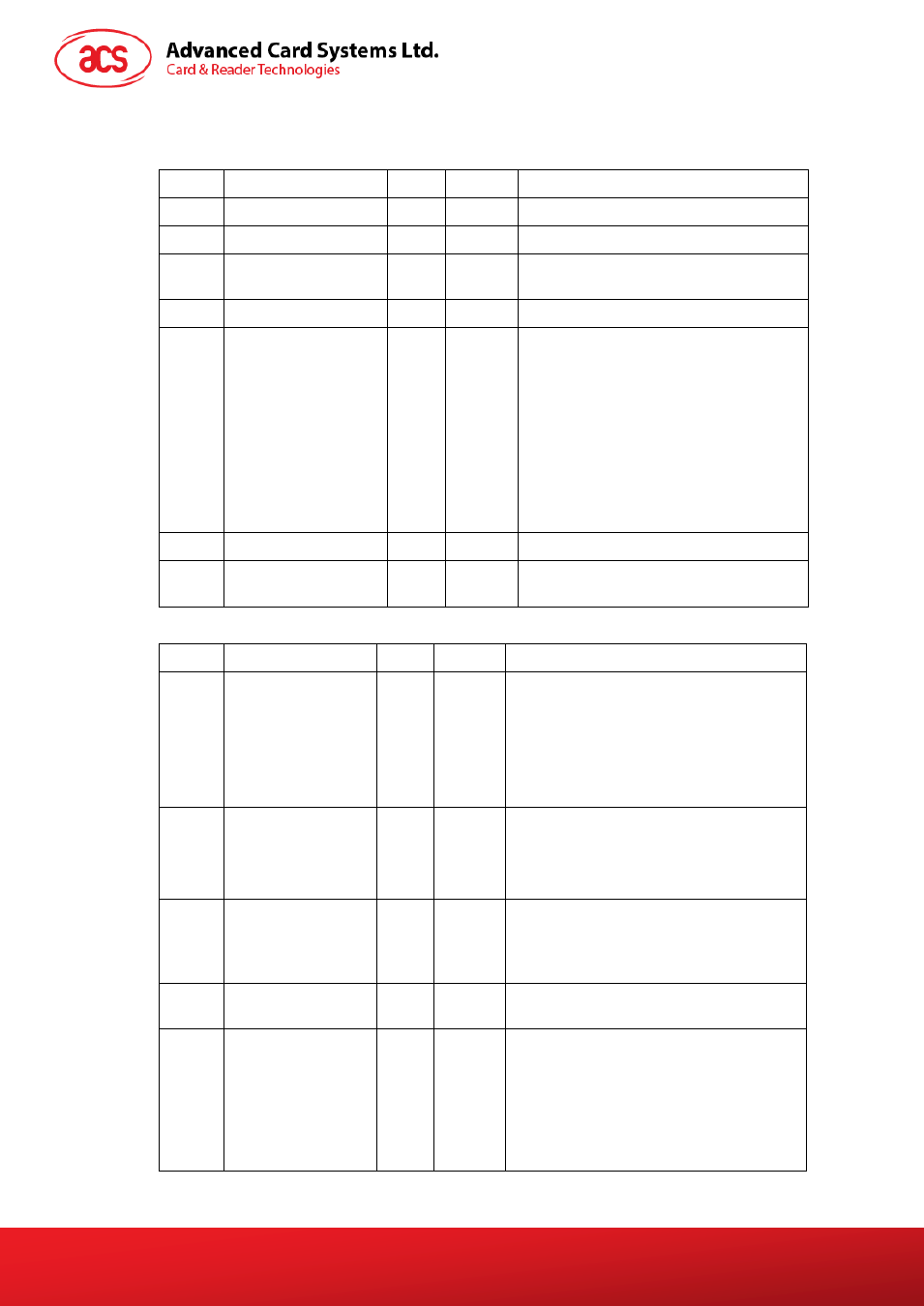
PC_to_RDR_SetParameters
Set slot parameters.
Offset
Field
Size
Value
Description
0
bMessageType
1
61h
1
dwLength
4
Size of extra bytes of this message
5
bSlot
1
Identifies the slot number for this
command
6
bSeq
1
Sequence number for command
7
bProtocolNum
1
Specifies what protocol data structure
follows.
00h = Structure for protocol T=0
01h = Structure for protocol T=1
The following values are reserved for
future use.
80h = Structure for 2-wire protocol
81h = Structure for 3-wire protocol
82h = Structure for I2C protocol
8
abRFU
2
Reserved for future use
10
abProtocolDataS
tructure
Byte
array
Protocol Data Structure
Protocol Data Structure for Protocol T=0 (dwLength=00000005h)
Offset
Field
Size
Value
Description
10
bmFindexDindex
1
B7-4
– FI – Index into the Table 7 in
ISO/IEC 7816-3:1997 selecting a clock
rate conversion factor
B3-0
– DI - Index into the Table 8 in
ISO/IEC 7816-3:1997 selecting a baud
rate conversion factor
11
bmTCCKST0
1
B0
– 0b, B7-2 – 000000b
B1
– Convention used (b1=0 for direct,
b1=1 for inverse) Note: The CCID
ignores this bit.
12
bGuardTimeT0
1
Extra Guardtime between two
characters. Add 0 to 254 etu to the
normal guardtime of 12etu. FFh is the
same as 00h.
13
bWaitingIntege
rT0
1
WI for T=0 used to define WWT
14
bClockStop
1
ICC Clock Stop Support
00h = Stopping the Clock is not allowed
01h = Stop with Clock signal Low
02h = Stop with Clock signal High
03h = Stop with Clock either High or Low