Using micro display – ACR&Artex Vecta3 User Manual
Page 9
Y1-03-0235-1C
9
When determining bearing you can fine tune your bearing by using the
MICRO scale and looking for the highest power reading, slowly
scanning from left and right. You should see where the power starts to
drop off from the highest power reading and proceed forward in that
highest readings’ direction. Walking or not holding the Vecta™
3
in its
operation position can be misleading when trying to read the display.
Ensure that you are always in the operating position when recording
power measurements.
Polarizing the beacon and the Vecta™
3
The ability of the Vecta™
3
to pick up a weak signal is improved when
the antenna of the Vecta™
3
is oriented in the same polarization as the
antenna of the transmitter.
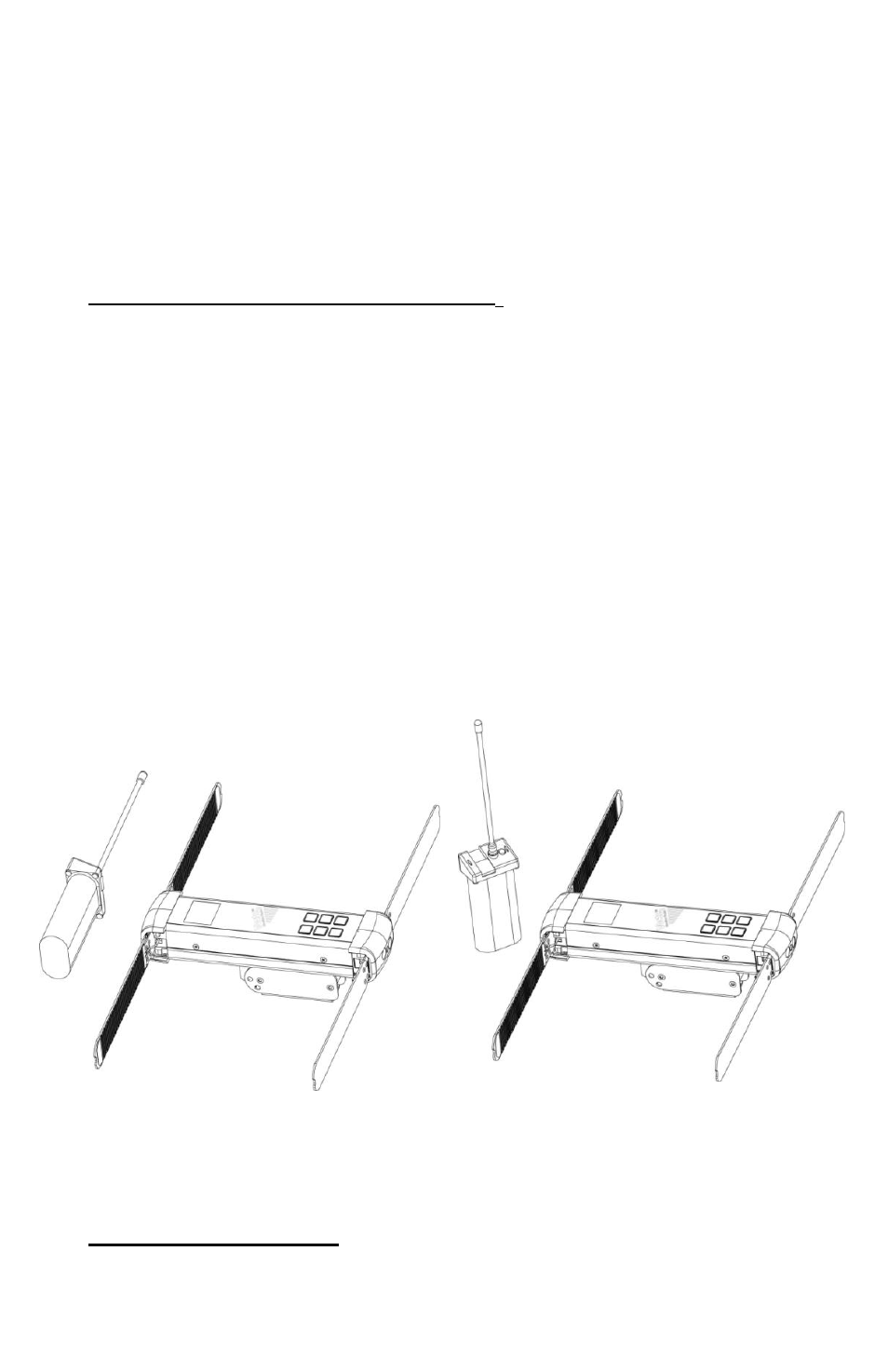
In a blind search, the polarization of the beacon’s antenna is unknown.
The beacon could be standing up or laying down. To polarize the
antennas, rotate the Vecta™
3
antennas from a horizontal position to a
vertical position so they are in alignment with th
e transmitting beacon’s
antenna. The Vecta™
3
is not polarized when the antenna blades of the
unit are in a perpendicular orientation with respect to the transmitting
antenna.
The Vect
a™
3
is polarized for maximum signal strength when the
antenna blades of the unit are in a parallel orientation with the transmit
antenna.
Once the tone is heard and the rescuer is heading in the direction of the
beacon, the NUMBER screen or MICRO screen can be expected to
increase the signal strength readout, showing that the beacon is nearer.
The audio tone will remain constant.
Using MICRO display
The MICRO display uses a bar graph to display beacon signal strength.
Before switching to this view, first determine from the NUMBERS view
Figure 4
Polarized with Beacon
Figure 5
Not Polarized with Beacon