Product layout & functions, Operation guide, Figure 4 – Acclaim Lighting X-Power HP Pro User Manual
Page 6: 1 front panel layout, Pin xlr to 5-pin xlr conversion, Pin xlr dmx connectors, 2stand alone mode, 2 rear panel layout, 1 dmx control mode (dmx addressing)
1=Ground; 2=Data
; 3=Data+
-
DMX OUT
ON
OFF
1 2
3
DMX IN
1 2
3
1
2
3
4
5
6
OUTPUT: 3x350mA
per output
DMX Address Setting
1 2 3 4 5 6 7 8 9 10
1
2
4
8
16
32
64
128
256
MODE
1 2
NC
3
6
4 5
OUTPUT
1 2 3 4 5 6
1 2 3 4 5 6
1 2 3 4 5 6
Manual DIM
STAND ALONE
( Dipswitch 10 = OFF )
#1 - 3 Fade time
#4 - 6 Speed
#7 - 9 Program
MANUAL
#1 - 8
Level 0-255
( Dipswitch 6
= ON )
18 LEDs With 6 Ports (1), (2), (3), (4), (5), (6);
36 LEDs With 3 Ports (1, 2), (3, 4), (5, 6).
Termination reduces signal errors and avoids signal transmission
problems and interference. It is always advisable to connect a
DMX terminal, (Resistance 120 Ohm 1/4 W) between PIN 2 (
DMX-) and PIN 3 (DMX +) of the last fixture.
Figure 4
4.Product Layout & Functions
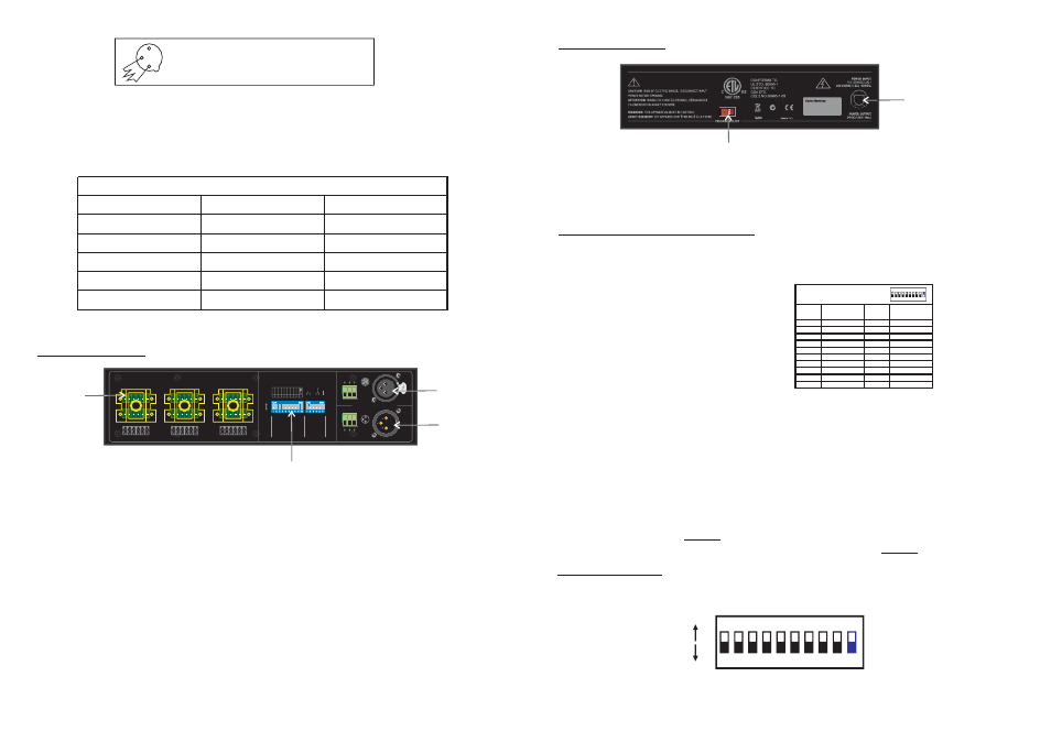
Flip 10-way and 6-way Dip Switches to set some functions and modes for user's desired effects.
3-Pin XLR male connector or terminal. Connect a universal DMX controller into this input for receiving DMX
values or DMX signals.
3-Pin XLR female connector or terminal. Connect to next DMX fixtures for sending DMX values or DMX
signals.
6 terminal output connectors, allows a maximum loads of 3x350mA per output and the maximum amount
connected loads distributed over all 6 outputs must not exceed 6A.
1. Dip Switches(10-way and 6-way):
2. DMX Input:
3. DMX Output:
4. Output:
-3-
4.1 Front Panel Layout
1
2
3
3-Pin XLR to 5-Pin XLR Conversion
Conductor
Ground/Shield
Data Compliment(-signal)
Data True(+signal)
Not Used
Not Used
3-Pin XLR Female(Out)
Pin 1
Pin 2
Pin 3
5-pin XLR Male(In)
Pin 1
Pin 2
Pin 3
Pin 4 - Do Not Used
Pin 5 - Do Not Used
5-Pin XLR DMX Connectors.
Some manufactures use 5-pin XLR connectors for DATA transmission in place of 3-pin. 5-pin XLR fixtures
may be implemented in a 3-pin XLR DMX line. When inserting standard 5-pin XLR connectors in to a 3-pin
line a cable adaptor must be used, these adaptors are readily available at most electric stores. The chart
below details a proper cable conversion.
1
4
2
3
5.2Stand Alone Mode
The Stand Alone Mode is engaged in by flipping the dip-switch 10 to the "OFF" position. And this mode includes
sub-modes with many functions, such as fade time, chasing speed, built-in programs.
1 2 3 4 5 6 7 8 9 10
ON
RS
ON
OFF
1,2,4
3,4
1,3,4
2,3,4
1,2,3,4
1,2,3,4,5,6,7,8,9
1
2
1,2
3
1,3
2,3
1,2,3
4
1,4
2,4
DMX ADDRESS (SLAVE)
SWITCHES ON
SWITCHES ON
(Dip Switch 10 = on)
START
CH#
START
CH#
1
2
3
4
5
6
7
8
9
10
11
12
13
14
15
..
511
..
..
..
..
..
..
..
1 2 3 4 5 6 7 8 9 10
ON
RS
DMX is short for Digital Multiplex. This is a universal binary language used as a form of communication
between intelligent fixtures. Each dip switch represents a binary value.
5.Operation Guide
A DMX value(address) is set by combining the different dipswitches that will add up to the value you wish to
achieve, for example:
Setting DMX address for 21.
Flip switches1,3,&5 to the
"ON" position
Setting DMX address for 201.
Flip switches1,4,7,& 8 to the
"ON" position
Dipswitches#
Value
1=1
3=4
5=16
=21
Dipswitches#
Value
1=1
4=8
7=64
8=128
=201
-4-
4.2 Rear Panel Layout
1. Power Input: AC110~120V(3.2A)/AC220-240V(1.6A), 50~60Hz.
2. Voltage Selector:AC120V/230V optional by this voltage selector.
In this mode, the dip-switch 10 is flipped to the "ON" position. And this switch sometimes used to activate
some fixture special functions.
Dip Switch 1 address equals 1
Dip Switch 2 address equals 2
Dip Switch 3 address equals 4
Dip Switch 4 address equals 8
Dip Switch 5 address equals 16
Dip Switch 6 address equals 32
Dip Switch 7 address equals 64
Dip Switch 8 address equals 128
Dip Switch 9 address equals 256
5.1 DMX Control Mode(DMX Addressing)
1
2