Installation guide ccr3 controller – Danfoss CCR3 Controller User Manual
Page 7
Installation Guide
CCR3 Controller
77
Heating Solutions
VI.D3.A2.02
DEN-SMT/SI
No
LCD Display
BASIC MENu - FuNCtION DESCRIPtION
24
TRet (80)
.....
Required return temperature for measure supply temperature: 80 °C
Factory setting: 54 °C
25
TRet (90)
.....
Required return temperature for measure supply temperature: 90 °C
Factory setting: 58 °C
26
Shift1
..0 °C..
Shift return temperature valid for all setting points. It can be adjusted up and down. The lowest shift setting
is to 10 degrees (anti frost setting value).
Each riser can be adjusted individually, riser by riser (from 1 to 16)
Factory setting: 0 ºC; in range of ±10 °C
27
RiserNr
16
Number of risers used in the system: settings from: 1-16
If more than 16 risers: choose 16 and connect selected risers parallel using one actuator’s output for two risers
(for two actuators) (max additional 16 risers)
Factory setting: 16
28
Int.Time
…….
Integration time of the control signal (depend of actuators type). The shorter time, quicker temperature
changes (no stable regulation). The longer time slower reaction for temperature change (stable regulation).
Factory setting: 6 sec (for dedicated TWA-Z (NO) actuators); setting range 1-100
29
Prop.Fac
……
Control gain of control signal (depend on actuators type). The higher gain control the bigger valves reaction
(no stable regulation). The lower gain control weak reaction for temperature change (stable regulation).
Factory setting: 10 (for dedicated TWA-Z (NO) actuators); setting range 1-100
30
VType
…….
Type of control valves: normal open or normal closed
Option to choose: NO or NC
Factory setting: NO
31
VCharact
…….
Type of valves characteristic
Option to choose: Linear or Hyperbolic
Factory setting: Hyperbolic (setting for 24 VAC actuator)
32
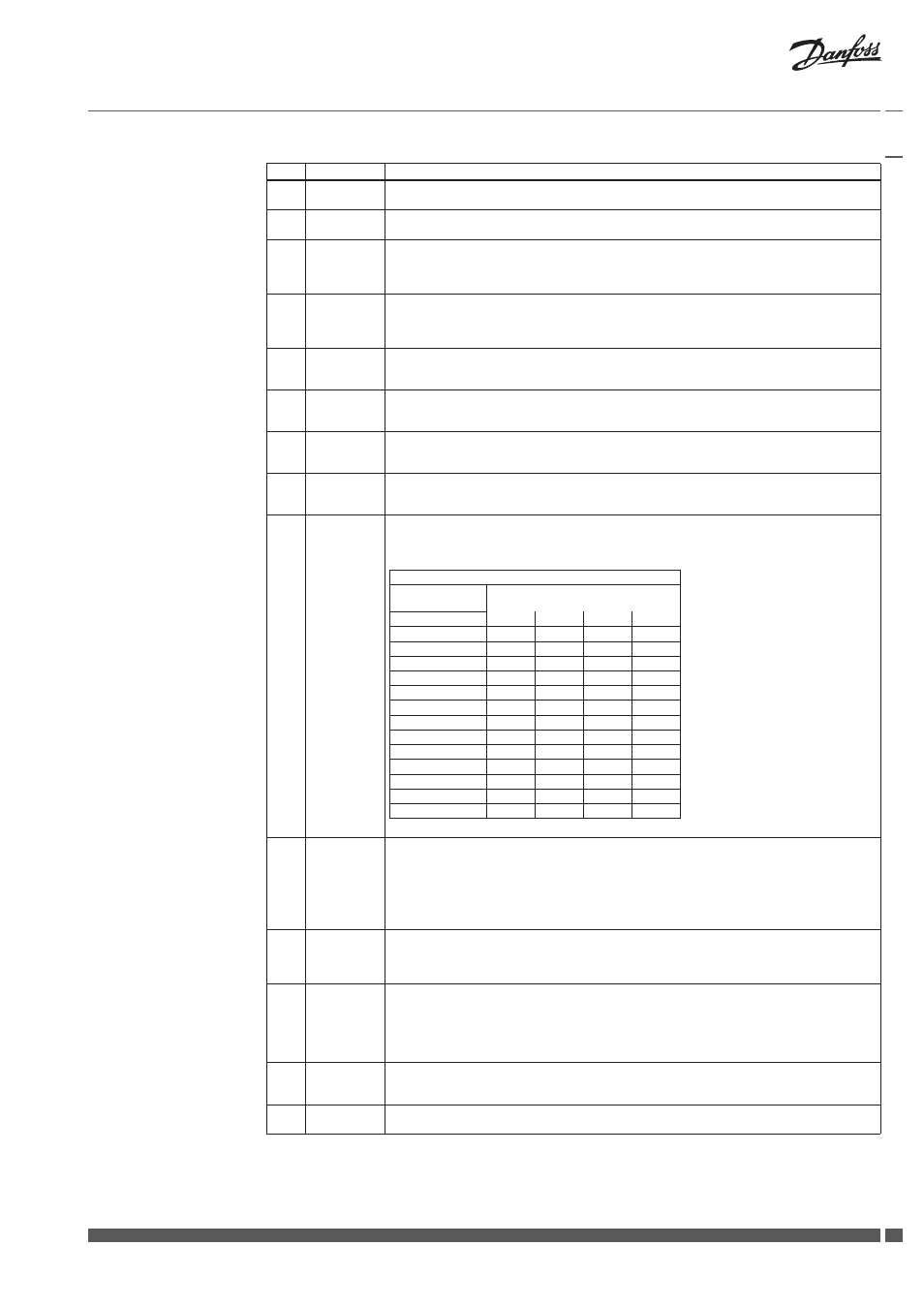
Cor Cal
S0 ….
…. °C
Sensor calibration: S0-S16 in range: ±9,9 °C
Do not make calibration when sensor cables are shorter then:
- for cable 0,75 mm
2
– 10 meters,
- for cable 1,00 mm
2
– 15 meters.
Correction factor
total length
(two - core cable)
cable cross section
(mm
2
)
in meter
0,5
0,75
1,00
1,5
10
- 0,2
- 0,1
- 0,1
- 0,1
15
- 0,5
- 0,3
- 0,2
- 0,1
20
- 0,4
- 0,3
- 0,2
- 0,1
25
- 0,5
- 0,3
- 0,3
- 0,1
30
- 0,6
- 0,4
- 0,3
- 0,2
35
- 0,7
- 0,5
- 0,4
- 0,2
40
- 0,8
- 0,5
- 0,4
- 0,2
45
- 0,9
- 0,6
- 0,5
- 0,2
50
- 1,0
- 0,7
- 0,5
- 0,3
75
- 1,5
- 1,0
- 0,8
- 0,4
100
- 2,0
- 1,4
- 1,0
- 0,5
125
- 2,5
- 1,7
- 1,3
- 0,6
150
- 3,0
- 2,0
- 1,5
- 0,8
Factory setting: 0 °C
33
Rel.Test
……….
Relay test (Triac output)
AUTO – normal working operation
V1-V16 – forced signal for valves output V1-V16
Rel C-NO - not used
T1 Out – not used
T2 Out – forced signal (24 VAC) for alarm T2.
Factory setting: Auto
34
AlertRel
... …
Alarm output (Triac)
StillOn – continuos alarm signal: T2 – 24 VAC
Pulse – pulse alarm signal 24 VAC every second
Factory setting: Pulse
35
Archiver
...
Information about data archiving:
Never – the feature is switched off,
1 File – data is stored in one file on the SD card,
2 Files – data is stored alternatively in two files to improve write reliability. This function decreases term of
date storage (twice).
Factory setting: 1 File
36
ArchFreq
...
Data archiving interval. The time can be set to any value between 10 seconds and 4 hours. The data from
each day saved in different files (with data name).
Factory setting: 1 min
37
BMSAdres
…..
CCR3 address in BMS system
Factory setting: 1