8 front panel display, Khz mhz – Walter Drake SW8 User Manual
Page 14
11) SW
METER - Indicates the Shortwave
band designators that define a range of frequencies for
each band as follows:
Shortwave Band Designators
120 METER: 2300 - 2500 kHz
90 METER: 3200 - 3400 kHz
75 METER: 3900 - 4000 kHz
60 METER: 4750 - 5060 kHz
49 METER: 5800 - 6200 kHz
41 METER: 7100 - 7600 kHz
31 METER: 9500 - 9900 kHz
25 METER: 11600 - 12100 kHz
22 METER: 13570 - 13870 kHz
19 METER: 15100 - 15800 kHz
16 METER: 17480 - 17900 kHz
13 METER: 21450 - 21850 kHz
11 METER: 25600 - 26100 kHz
12) AIR - Indicates that the Aircraft band (118 - 137
MHz) has been selected.
13) 7-Digit Readout - This display indicates the
operating frequency of the receiver. The frequency is
displayed in 'kHz' for the AM broadcast and Shortwave
bands. The FM and Aircraft band frequencies are
displayed in MHz. In the clock mode, these digits
indicate time in 24 hour format i.e. HH:MM. In the
TIMER mode, indicates time in 24 hour format i.e.
HH:MM. 'L' Indicates that Local Time is being dis-
played in the clock mode. If the 'L' is not illuminated,
alternate time is displayed in the clock display mode.
14) SCAN
S - Indicates that the receiver is in the
memory channel SCAN mode and displays the number
of the currently scanned channel, from 00 to 69. In the
MEMORY mode, the 'S' illuminates to indicate that a
particular memory channel will be skipped over when
the SCAN operation is activated.
15) 6.0 4.0 2.3 - Indicates which IF filter is selected.
There is no indication in the FM mode.
16) ST - Indicates that a stereo FM broadcast
station is tuned in when stereo headphones are
plugged into the receivers headphone jack.
1) Bar Graph - This bar graph display indicates the
relative received signal level in S-units and dB above S9.
Each S-unit between S1 and S9 equals an approximately
5 dB change in received signal strength. Each S-unit
above S9 equals an approximately 10 dB change in
received signal strength.
2) TIMER - This annunciator indicates the state of the
Timer as either Active or Inactive. Refer to the
'CLOCK AND TIMER FUNCTIONS' section of this
manual.
3) LOCK - When illuminated, this annunciator
indicates that the Main tuning wheel and keypad are
not active.
4) F Indicates that the
F
button has been pressed
on the keypad to enable the alternate functions
(printed in orange) of the keypad buttons to be active.
5) MEM
- This annunciator indicates current
memory location from 00 to 69. MEM will light when
the receiver enters the memory mode. Refer to the
'MEMORY FUNCTIONS' section of this manual.
6) BATT - When operating on internal batteries,
'BATT' blinks to indicate a low charge on batteries.
ATT Indicates that the built-in attenuator is acti-
vated.
7) AGC SF - Indicates the AGC setting, Slow or Fast.
8) AM SYNC - Indicates that the AM mode of recep-
tion is on. If SYNC is also illuminated, then the
synchronous AM mode of detection is on.
9) USB - Indicates that the Upper sideband mode of
detection is on.
LSB Indicates that the Lower sideband mode of
detection is on.
10) FM - Indicates that the FM mode of detection is
on. This mode is selectable only on the FM broadcast
band (87 - 108 MHz).
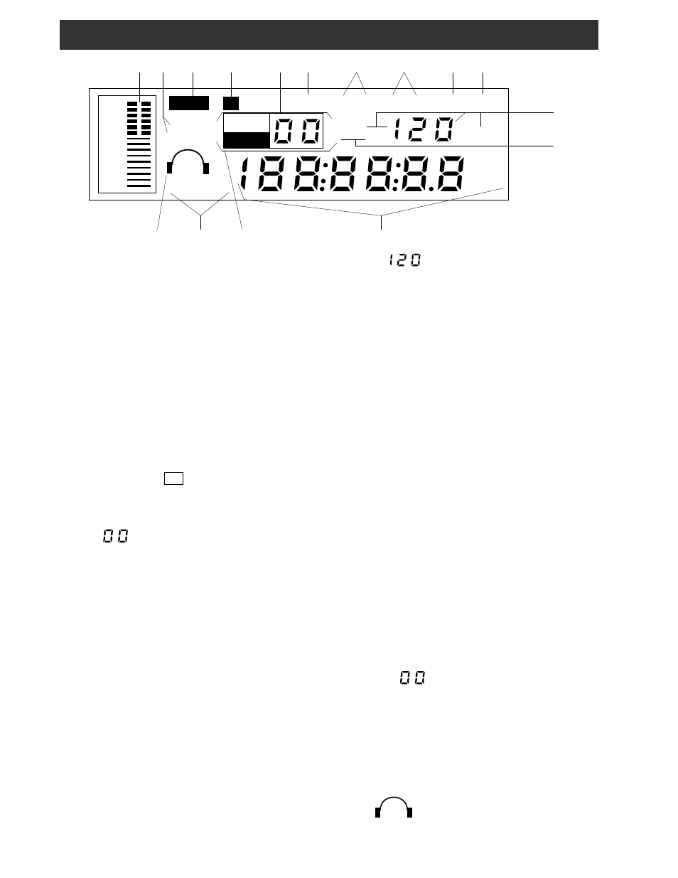
8 Front Panel Display
16 15 14 13
BATT AGC SF AM SYNC USB FM
METER
TIMER
ON OFF
+60
+40
+20
9
7
5
3
1
KHz
MHz
AIRSW
M E M
SCAN
S
LOCK
F
6.0 4.0 2.3
S T
L
1 2 3 4 5 6 7 8 9 10
11
12