4 installation – Walter Drake SW8 User Manual
Page 10
4 Installation
PORTABLE OPERATION
For use in a portable environment, the SW8 is oper-
ated from six (6) internally mounted D cell batteries.
These batteries are not supplied and must be installed
prior to portable operation of the SW8. See Figure
1
in
the `BATTERY INSTALLATION section of this
manual. For longest battery life, alkaline batteries are
recommended for this product.
NOTE: REMOVE THE BATTERIES IF THE SW8 IS
TO BE STORED OR OTHERWISE NOT OPERATED
FOR AN EXTENDED PERIOD OF TIME TO AVOID
DAMAGE TO THE SW8 DUE TO POSSIBLE BAT-
TERY LEAKAGE OR CORROSION EFFECTS. The
SW8 does not rely on the batteries for retention of
memory channels. To insure that the clocks and
timers are maintained following a loss of AC power or
battery removal, the SW8 must first be connected to
an AC power source or have batteries installed for a
minimum of 10 minutes. If power is lost after this
minimum 'charge' time, clocks and event timer settings
are maintained for a period of approximately 30
minutes.
ANTENNA REQUIREMENTS
(Refer to Figure 3, page 5)
The SW8 incorporates rear panel switches to select
between the internal whip antenna and various types of
external antennas. The built-in WHIP antenna is
available for use on all bands. For 500 kHz to 30 MHz
operation, two antenna connectors are also provided.
ANTENNA
1
is a 50 ohm, SO-239 coaxial input
requiring a mating PL-259 connector. This input would
typically be used as the primary AM broadcast and
shortwave band antenna input. Antennas such as
dipoles, trap dipoles, verticals and beams will provide
the best results depending upon the desired receiving
frequency. ANTENNA 2 is a compression terminal
type connection, providing a choice of high-impedance
(500 ohms typical) or low-impedance (50 ohms
typical). Antennas such as long wires or end-fed Zepps
will provide the best results. For reception in the 87-
108 and 118-137 MHz range, the FM/AIR terminals
are also provided. Outside TV antennas, folded dipoles
or coaxial antennas will provide the best results with
this input for reception of the FM broadcast and
Aircraft bands. Depending upon the particular type of
antenna feed, connect to one of the 'FM/AIR' terminals
and the 'GND'terminal for an unbalanced 75 ohm
input, or, connect to the two '300 ohm' terminals for a
balanced 300 ohm input. The best antenna for any of
the previously mentioned inputs will depend on the
frequency range and time of day for the particular
signal in question. Refer to publications such as the
ARRL Handbook or ARRL Antenna Manual (available in
most public libraries) for help on selection and/or
construction of the antennas mentioned above.
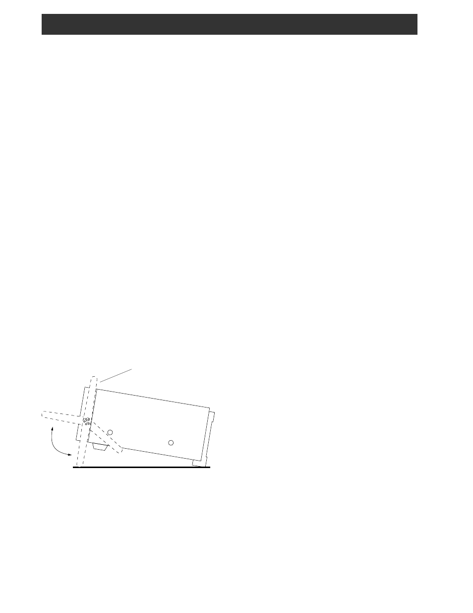
FIGURE 2 - ADJUSTING CARRYING HANDLE
Side View of SW8
FIXED INSTALLATION
After unpacking the unit, connect the antenna system
to the appropriate antenna input. Connect system
ground to the compression terminal marked GND.
Plug the output cable of the AC Adaptor into the
External DC Input connector on the rear panel of the
SW8 receiver. Plug the AC Adaptor into a source of
120 VAC, 60 Hz power. Refer to Figure 3 for the
diagram of a typical fixed installation.
UNPACKING
Carefully remove the SW8 and included AC Adaptor
wall transformer from the shipping carton and examine
them for evidence of damage. If any damage is noted,
immediately contact the transportation company
responsible for delivery or return the unit to the dealer
from whom it was purchased. Keep the shipping
carton and all packing material for the transportation
company to inspect. The original carton and packing
material should be retained for repackaging should it be
necessary to return the receiver. Inspect the packing
material for any accessories or printed material before
storing the box. Locate the registration card, fill it out,
and immediately return it to the R.L. Drake Company
to insure registration and validation of warranty.
LOCATION
The location of the SW8 is not critical. For added
operating convenience, the carrying handle may be
adjusted to elevate the front of the unit or positioned
behind the front feet. To adjust the handle, disengage
the detents at both sides of the handle at its pivot
points and adjust to desired position until detents are
engaged. To detach (or reinstall) handle from the
receiver, adjust handle to the vertical up position and
bow handle outward at both sides. See Figure 2.
For fixed locations, the SW8 should be operated from
the AC Adaptor. Keep curtains and other flammable
material away from direct contact with the AC Adaptor
to avoid overheating the transformer which could
result in failure or fire.
Vertical Up Position