Warning, Securing drum wraps, Rear support – Wayne-Dalton TORQUE MASTER PLUS 9400 User Manual
Page 6
black tooth on the ratchet wheel or the mark on the winding shaft. Rotate the winding shaft to
the required number of turns for your door. Then return to the right hand side and wind the right
hand spring to the required number of turns. Place pawl knob in lower position on both sides.
IMPORTANT: MARK nuMBER Of SPRInG TuRnS On TORQuEMASTER
®
PluS EnD BRACKET
WARnInG TAG.
NOTE: Since total turns to balance door can deviate from spring turn chart values by ± 1/2
turn, adjustments to the recommended number of turns may be required after rear supports are
installed.
IMPORTANT: HOlD THE DOOR DOWn TO PREVEnT IT fROM RISInG unExPECTEDlY In THE
EVEnT THE SPRInG WAS OVER-WOunD AnD CAuTIOuSlY REMOVE VICE ClAMPS fROM VERTI-
CAl TRACKS.
Ratchet wrench
with 3” extension
and 5/8” socket
End bracket
Winding
shaft
Marks
Black tooth on
ratchet wheel
Pawl knob in
lower position
Pawl knob in
upper position
sPRING TuRN ChART
DOOR HEIGHT
SPRInG TuRnS
6’-0”
14
6’-3”
14-1/2
6’-5”
15
6’-6”
15
6’-8”
15-1/2
6’-9”
15-1/2
7’-0”
16
7’-3”
16-1/2
7’-6”
17
7’-9”
17-1/2
8’-0”
18
securing Drum Wraps
Tools: Step Ladder
26
un-snap the drum wrap hinged latch and rotate down.
IMPORTANT: Pull THE COunTERBAlAnCE CABlE AWAY fROM THE HEADER TO ClEAR THE
lATCH, WHIlE SIMulTAnEOuSlY SlIDInG THE DRuM WRAP AGAInST THE lAST RIB unTIl THE
THREE CATCHES EnGAGE THE 3RD RIB.
Re-engage the hinge latch by rotating upward until a distinct snap is felt. Confirm the catch is
fully engaged by lightly tugging on it. Repeat for the other side.
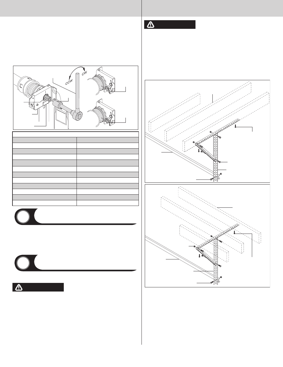
Rear support
Tools: Ratchet wrench, Socket: 1/2”, 5/8”, Wrench: 1/2”, 5/8”, (2) Vice
clamps, Tape measure, Level, Hammer, Step Ladder
27
Raise the door until the top section and half of the next section are in a horizontal position. Do
not raise door any further since rear of horizontal track is not yet supported.
WARNING
WARNING
RAIsING DOOR fuRThER CAN REsuLT IN DOOR fALLING AND CAusE sEvERE
OR fATAL INjuRy.
Clamp a pair of vice clamps on the vertical tracks just above the second roller on one side, and
just below the second roller on the other side. This will prevent the door from raising or lowering
while installing the rear support.
using perforated angle (may not be supplied), (2) 5/16”-1- 5/8” hex head lag screws and (3)
5/16” bolts with nuts (may not be supplied), fabricate rear support for horizontal tracks. Attach
horizontal tracks to the rear supports with 5/16”-18 x 1 hex bolts and nuts (may not be sup-
plied). Horizontal tracks must be level and parallel with door within 3/4” to 7/8” maximum of
door edge.
NOTE: If an idrive
®
opener is installed, position horizontal tracks one hole above level when
securing it to the rear supports.
WARNING
WARNING
kEEP hORIzONTAL TRACk PARALLEL AND WIThIN 3/4” TO 7/8” MAxIMuM Of
DOOR EDGE, OThERWIsE DOOR COuLD fALL, REsuLTING IN sEvERE OR fATAL
INjuRy.
IMPORTANT: DO nOT SuPPORT THE WEIGHT Of THE DOOR On AnY PART Of THE HORIzOn-
TAl TRACK HAnGER THAT CAnTIlEVERS 4” OR MORE BEYOnD A SOunD fRAMInG MEMBER.
NOTE: If rear supports are to be installed over drywall, use (2) 5/16” x 2” hex head lag screws
and make sure lag screws engage solid structural lumber.
NOTE: 26” angle must be attached to sound framing members and nails should not be used.
now, permanently attach the weather seal on both door jambs and header (temporarily attached
in Preparing the Opening, in the pre-installation section of this manual). Avoid pushing weather
seal too tightly against face of door.
5/16”-18 x 1-1/4”
Hex bolt must extend into the
track to serve as a roller stop
Perforated angle
Sound framing
members
Horizontal
track
(3) 5/16”
Bolts and nuts
Perforated angle bolted
using (2) 5/16” x 1-5/8”
hex head lag screws to
ceiling member and
parallel to door
Perforated angle
Sound framing
members
Horizontal
track
(3) 5/16”
Bolts and nuts
Perforated angle bolted
using (2) 5/16” x 1-5/8”
hex head lag screws to
ceiling member and
parallel to door
5/16”-18 x 1-1/4”
Hex bolt must extend into the
track to serve as a roller stop
6
Please Do not Return This Product To The Store. Contact your local Wayne-Dalton dealer. To find your local Wayne-Dalton dealer,
refer to your local yellow pages business listings or go to the find a Dealer section online at www.wayne-dalton.com