Optional installations, Trolley arm configuration – Wayne-Dalton TORQUEMASTER 9600 User Manual
Page 8
or TorqueMaster® Plus operation problems.
Close the door and place vice clamps onto both vertical tracks just above the third roller. This is
to prevent the garage door from raising while adjusting the counterbalance spring(s).
IMPORTANT: TO ADjuST SPRInGS, OnlY ADD OR REMOVE A MAxIMuM Of 3/10 Of A TuRn
(THREE TEETH On THE RATCHET WHEEl) AT A TIME. BOTH SIDES nEED TO BE ADjuSTED
EQuAllY On DOuBlE SPRInG DOORS.
Add spring tension: The ratchet wheel is made of 10 teeth. To add spring tension, ensure the
ratchet and socket is set so that it will tighten counter clockwise on the right hand side and
clockwise on the left hand side. Place the ratchet wrench with 5/8” socket and 3” socket exten-
sion onto the winding shaft, pull down to add 3/10 of a turn. Watch as three teeth of the ratchet
wheel pass over the pawl, creating three “clicks”.
Remove spring tension: To remove spring tension, place a regular 5/8” wrench onto the winding
shaft. Pull down on the wrench to relieve pressure between the pawl and the ratchet wheel.
Push in on the pawl to allow the three ratchet wheel teeth to pass by the pawl, as you carefully
allow the wrench to be rotated upward by the spring tension, release the pawl to allow it to
engage with the ratchet wheel.
IMPORTANT: BE PREPARED TO HOlD THE full TEnSIOn Of THE SPRInG.
IMPORTANT: DO nOT ADD OR REMOVE MORE THAn 1 SPRInG TuRnS (1 SPRInG TuRn
EQuAlS 10 TEETH On RATCHET WHEEl) fROM THE RECOMMEnDED nuMBER Of TuRnS
SHOWn On THE SPRInG TuRn CHART.
If the door still does not operate easily, lower the door into the closed position, unwind spring(s)
completely, and recheck the following items:
1.) Check the door for level.
2.) Check the TorqueMaster® spring tube and flag angles for level and plumb.
3.) Check the distance between the flag angles, which must be door width plus 3-3/8” to
3-1/2”.
4.) Check the counterbalance cables for equal tension; adjust if necessary.
5.) Rewind the spring(s).
6.) Make sure door isn’t rubbing on jambs.
NOTE: If an idrive® opener was installed and you have completed this step, refer to the idrive®
Installation Instructions and Owner’s Manual to complete your idrive® installation.
oPTIonal InsTallaTIons
Trolley Arm Configuration
Tools: Tape measure, Level
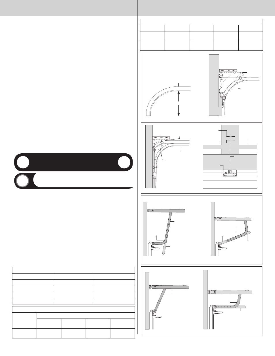
Measure the curved ends of the horizontal track to determine if you have a 12” or 15” radius
horizontal track, as shown in fIG 1; if you have a low headroom door skip this step. Determine
center line of the door. Mark vertical line at this point on the header, as shown in fIG 4. Raise
the door slightly until the top section reaches the highest point of travel (high arc), as shown in
fIG 2 and fIG 3 for low headroom. using a level, mark this high arc point on the header where it
intersects the vertical center line, as shown in fIG 4. Hold the wall bracket’s bottom edge 1/2” -
1” (room permitting) above the high arc line and centered on the vertical center line, as shown in
fIG 4. Mark the wall bracket’s mounting holes on the header wall and then refer to your garage
door operator manual for pre-drilling and securing the wall bracket to header.
using the operator hook-up charts, refer to referenced illustrations for correct arm hook-up from
trolley to operator bracket. for low headroom, refer to operator hook-up chart for low headroom.
note: Refer to your operator manual for specific details on how to assembly the curved and
straight arm, as shown in fIG 5 and fIG 6, and fIG 7 and fIG 8 for low headroom.
NOTE: Depending on your setup, you may or may not have to cut straight arm to accomplish
trolley settings.
Align hole in the appropriate arm with holes in operator bracket tabs, as shown in step, Trolley
Arm Hookup. Insert 5/16” x 1-1/4” clevis pin, making sure hole in clevis pin is outside of second
tab of operator bracket. Insert cotter pin into clevis pin hole and spread hairpin cotter to ensure
it will secure assembly.
OPERATOR HOOK-uP CHART,STAnDARD lIfT fOR 12” AnD 15” RADIuS
OPERATOR MODElS
TYPE Of ARM BEInG uSED
REf. IlluSTRATIOnS
QuAnTuM/ClASSIC
CuRVED / STRAIGHT
fIG 6
lInEAR
STRAIGHT / CuRVED
fIG 5
lIfTMASTER (SEARS)
CuRVED / STRAIGHT
fIG 6
GEnIE
CuRVED / STRAIGHT
fIG 6
OPERATOR HOOK-uP CHART fOR lOW HEADROOM
OPERATOR
MODElS
TYPE Of ARM BEInG uSED
PREfERRED
HOOKuP
REf. IlluSTRA-
TIOnS
OPTIOnAl
HOOK-uP
REf. IlluSTRA-
TIOnS
QuAnTuM /
ClSSSIC
CuRVED /
STRAIGHT
fIG. 8
STRAIGHT
fIG. 7
OPERATOR HOOK-uP CHART fOR lOW HEADROOM
lInEAR
STRAIGHT
fIG. 7
n/A
n/A
lIfTMASTER
(SEARS)
CuRVED /
STRAIGHT
fIG. 8
STRAIGHT
fIG. 7
GEnIE
CuRVED /
STRAIGHT
fIG. 8
STRAIGHT
fIG. 7
FIG 1
12” or 15”
FIG 2
Horizontal
track
Level
High arc
Top section
High arc
FIG 4
FIG 3
TorqueMaster
®
counterbalance
Vertical
center line
From step
Typical 1/2”-1”
above high arc
High arc line
Header
Top section
Low headroom track
Level
Cut straight arm to
accomplish trolley
setting
FIG 6
FIG 5
Curved arm
Curved arm
Cut straight arm to
accomplish trolley
setting
Straight arm
Straight arm
Curved arm
Straight arm
FIG 8
FIG 7
Cut straight arm to
accomplish trolley setting
8
Please Do not Return This Product To The Store. Contact your local Wayne-Dalton dealer. To find your local Wayne-Dalton dealer,
refer to your local yellow pages business listings or go to the find a Dealer section online at www.wayne-dalton.com