Attaching u-bars, Roller slides – Wayne-Dalton TORQUEMASTER 9600 User Manual
Page 3
ING jAMb bRACkETs
Tools: Tape Measure
4
ATTACh-
NOTE: Windload specification 0356 only uses the (Q.I.) jamb bracket schedule.
NOTE: The following (Q.I.) denotes a quick install jamb bracket. no additional hardware is
needed.
NOTE: The following (jB-1) denotes a slotted jamb bracket.
Measure the length of the vertical tracks. using the jamb bracket schedule, determine the place-
ment of the jamb brackets for your door height and track length.
TO INsTALL ThE (Q.I.) jAMb bRACkETs:
Align the twistlock tab on (Q.I.) jamb bracket with the quick install feature in the track and turn
the jamb bracket perpendicular to the track so the mounting flange is toward the back leg of the
track.
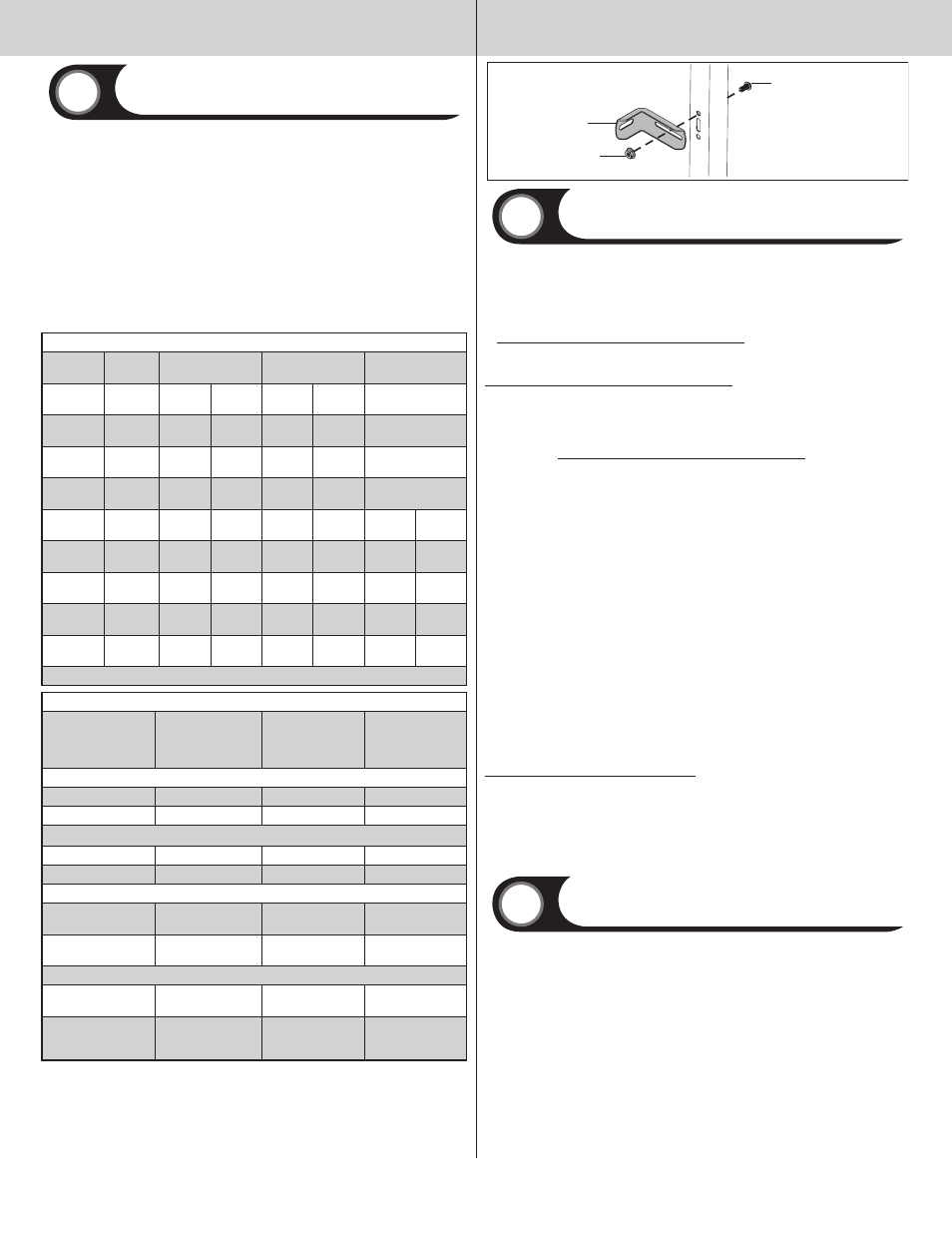
TO INsTALL ThE (jb-1) jAMb bRACkETs:
loosely fasten the (jB-1) jamb bracket to the track with a (1) 1/4”-20 x 9/16” track bolt and (1)
1/4”-20 flange hex nut.
(Q.I.) jAMb bRACkET sChEDuLE
DOOR HEIGHT
TRACK
lEnGTH
1ST SET
2nD SET
3RD SET
6’0”
64” (1626
mm)
5
M
6
B
nA
6’5”
69” (1753
mm)
3
B
6
M
nA
6’8”
72” (1829
mm)
3
B
6
M
nA
7’0”
76” (1930
mm)
3
B
7
T
nA
7’3”
79”
(2007mm)
3
B
5
B
6
B
7’6”
82” (2083
mm)
3
B
5
B
6
B
7’9”
85” (2159
mm)
3
B
5
B
6
B
8’0” 4-SEC
88”
(2235mm)
3
M
6
T
7
M
8’0” 5-SEC
88” (2235
mm)
3
B
7
T
8
T
B= BOTTOM HOlE, M= MIDDlE HOlE, T= TOP HOlE
(jb-1) jAMb bRACkET sChEDuLE
Door height
no. of sections
no. of jamb brackets
(each jamb)
location of center line of
jamb brackets measured
from bottom of track (all
dimensions ±2”)
WINDLOAD sPECIfICATION 0228
7’-0” or less
4
1
2” (jB-1), 63” (jB-1)
7’-1’’ to 8’-0”
4 or 5
1
2” (jB-1), 34” (jB-1)
WINDLOAD sPECIfICATION 0229, 0600, 0602, & 0606
7’-0” or less
4
2
25-1/2” (jB-1), 63”(jB-1)
7’-1’’ to 8’-0”
4 or 5
2
23” (jB-1), 34” (jB-1)
WINDLOAD sPECIfICATION 0235, 0236, 0237, 0604, & 0609
7’-0” or less
4
3
2” (jB-1), 25-1/2” (jB-1),
63”(jB-1)
7’-1’’ to 8’-0”
4 or 5
3
2” (jB-1), 23” (jB-1),
34” (jB-1)
WINDLOAD sPECIfICATION 0230, 0232, 0233, 0234, 0601, 0603, 0605, 0607, & 0608
7’-0” or less
4
4
2” (jB-1), 25-1/2” (jB-1),
34” (jB-1), 63” (jB-1)
7’-1’’ to 8’-0”
4 or 5
5
2”(jB-1), 23” (jB-1), 34”
(jB-1), 58” (jB-1), 75”
(jB-1)
Jamb bracket
(1) 1/4”- 20 X 9/16”
Track bolt
(1) 1/4”- 20
Flange hex nut
Attaching u-bars
Tools: Power Drill, 7/16” Socket Driver, Tape Measure
5
NOTE: Double car door struts are color coded. 18 gauge (.046) have red ends. 20 gauge (.034)
have blue ends.
NOTE: If your door’s windload option code is 0356 skip to that section of this step for u-Bar
attachment.
bottom section:
1.
If your doors windload option code begins with 06, place the u-Bar with the notched
ends over the bottom rib of the bottom section, notches facing down. Center u-Bar left to right
on section.
If your doors windload option code begins with 02, place the u-Bar with the notched ends
over the bottom rib of the bottom section, notches facing down. The end of the u-bar will fit
between the bottom bracket flange and the bottom section rib.
Center u-Bar left to right on section.
2. fasten the u-Bar at each end through the top flange with (1) 1/4”-14 x 7/8” self drilling
crimptite screw.
If your doors windload option code begins with 02, also fasten the u-bar
at each end to the bottom section rib with (2) 1/4”-14 x 5/8” self drilling crimptite screws,
through the two holes in the bottom bracket flange.
3. Place (2) 1/4”-14 x 5/8” self tapping screws through each pre-punched hole at each interme-
diate hinge location.
4. Place the u-Bar over the top rib of the bottom section with the eight pre-punched holes,
facing up. Center u-Bar left to right on section. Attach the u-Bar at each end through the bottom
flange with (1) 1/4”-14 x 7/8” self drilling crimptite screw.
5. finish securing the u-Bars to the section, by placing (2) 1/4” -14 x 5/8” self tapping screws
midway between the end of the door and intermediate hinge locations and (1) 1/4” -14 x 5/8”
self tapping screw approximately eight inches from each end.
Intermediate/ Top section(s):
1. Place the u-Bar over the top rib of each of the remaining sections with the (8) pre-punched
holes at the ends, facing up. Center u-Bar left to right on section.
2. fasten the u-Bar(s) at each end through the top and bottom flange with (2) 1/4”-14 x 7/8”
self drilling crimptite screw.
3. Place (2) 1/4”-14 x 5/8” self tapping screws through each intermediate hinge.
4. finish securing the u-Bar(s) to the section, by placing (2) 1/4” -14 x 5/8” self tapping screws
midway between the end of the door and intermediate hinge locations and (1) 1/4” -14 x 5/8”
self tapping screw approximately eight inches from each end.
Windload Option Code 0356.
If your doors windload option code is 0356, place the u-Bar over the top rib of the bottom
section. Center u-Bar left to right on section. fasten the u-Bar at each end with (2) 1/4”-14 x
5/8” self tapping screws through the top and bottom flange of the u-bar, as well as (2) 1/4”-14
x 5/8” self tapping screws at all intermediate hinge locations and midway between intermediate
hinge locations and end of u-Bar.
Attach u-Bar to the top rib of the intermediate section for a four section door and the top rib
of the intermediate and intermediate II sections for a five section door, in the same manner the
u-bar was attached to the bottom section.
Roller slides
Tools: Power Drill, 7/16” Socket Driver
6
Starting with the bottom section, place a roller slide on the top left side of the u-Bar and align
with the first set of holes (closest to the section) as shown. Attach the roller slide to the u-Bar
with
(2) 1/4”-14 x 5/8” self tapping screws. Repeat for opposite side. Install roller slides on the right
and left side of each u-bar, on all remaining sections with the exception of the top section.
A viewing hole on the roller slide will allow for correct positioning of roller
slide on u-bars. Place roller slides on the sections as follows:
lock Section (second section) use the second set of holes.
Intermediate Section(s) (Third and fourth section; Only a five section door will have a second
intermediate section) use the third set of holes for the third section and the fourth set of holes
for the fourth section.
fasten all roller slides to the u-bar with (2) 1/4”-14 x 5/8” self tapping screws.
3
Please Do not Return This Product To The Store. Contact your local Wayne-Dalton dealer. To find your local Wayne-Dalton dealer,
refer to your local yellow pages business listings or go to the find a Dealer section online at www.wayne-dalton.com