Appendix d: vortex output wiring, Cable drawing 1: vortex output to balanced input, Cable drawing 2: vortex output to unbalanced input – Vortex Media VTX 1000 User Manual
Page 100: D: v, Ppendix, Ortex, Utput, Iring
A
PPENDIX
D: V
ORTEX
O
UTPUT
W
IRING
C
ABLE
D
RAWING
1: V
ORTEX
O
UTPUT TO
B
ALANCED
I
NPUT
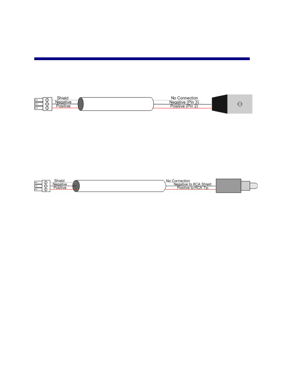
The above diagram illustrates the use of an XLR connector. Connect the Positive conductor of the Vortex
device to Pin 2 of the XLR connector, the Negative conductor of the Vortex device to Pin 3 of the XLR
connector, and the Shield of the cable to the only to the Vortex device.
C
ABLE
D
RAWING
2: V
ORTEX
O
UTPUT TO
U
NBALANCED
I
NPUT
Connect the Positive conductor of the Vortex device to the Tip of the RCA connector and the Negative
conductor of the Vortex device to Shield of the RCA connector. The shield of the cable is not connected at
the unbalanced end.
100