Velodyne Acoustics HDL-64E S2 User Manual
Page 16
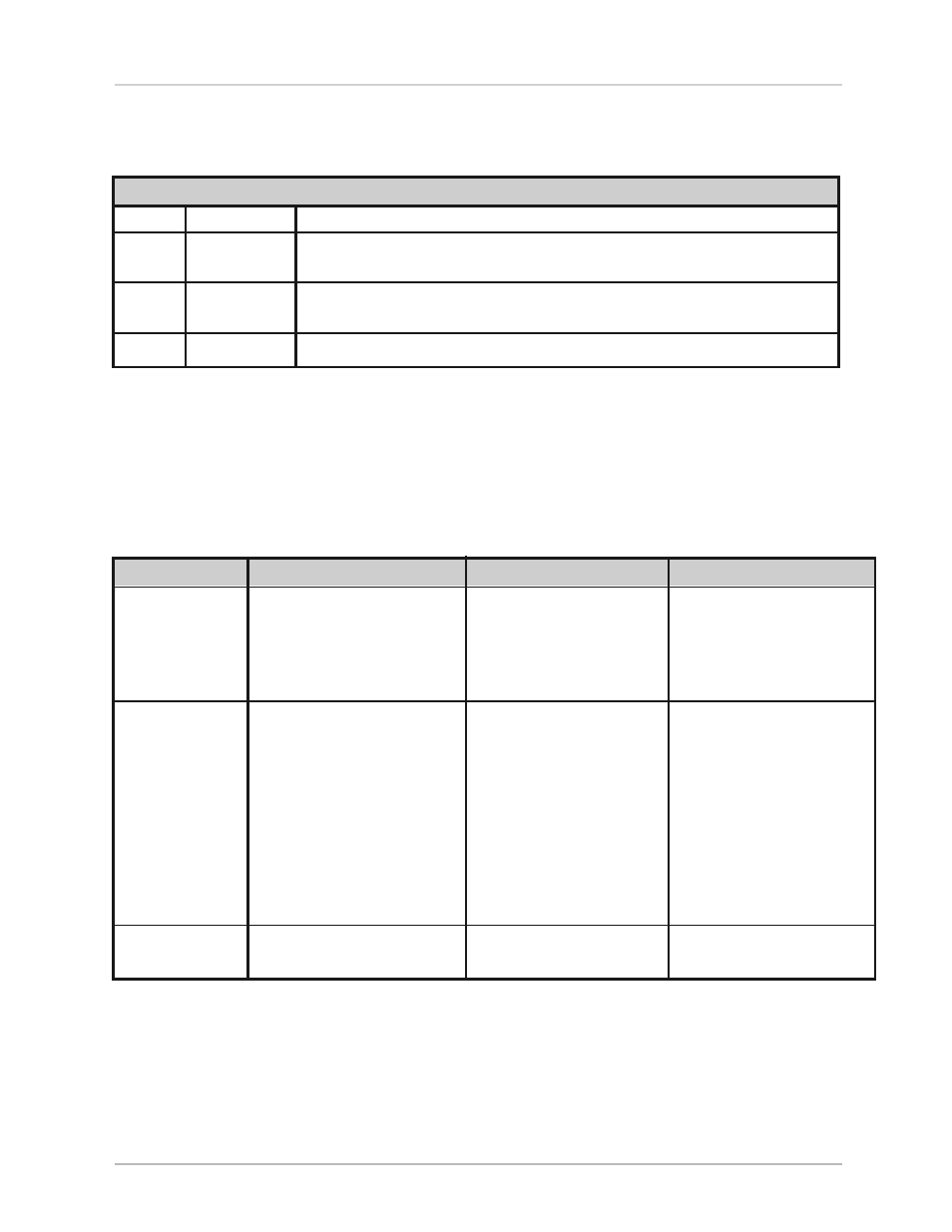
Packet Format and Status Byte for GPS Time Stamping
The 6 bytes at the end of the data packet report GPS timing and synchronization data. For every packet, the last 6 bytes are formatted
as follows:
Timestamp Bytes in Reverse Order in Microseconds
Bytes
Description
Notes
4
GPS timestamp
32 bit unsigned integer timestamp. This value represents microseconds from the top
of the hour to the first laser firing in the packet.
1
Status Type
8 bit ASCII status character as described in Appendix E. The status byte rotates
through many kinds of sensor information.
1
Status Value
8 bit data as described in Appendix E.
Within the GPS status byte, there are 4 GPS status indicators:
• 0: no GPS connection.
• A: both PPS and GPS command have signal.
• V: only GPS command signal, no PPS.
• P: only PPS signal, no GPS time command.
Time Stamping Accuracy Rules
The following rules and subsequent accuracy apply for GPS timestamps:
GPS Connection
Timestamp Info
Accuracy
Notes
GPS isn’t connected
The sensor starts running on
Expect a drift of about 5
The sensor clock does not correct
(GPS Status 0)
its own clock starting at midnight
seconds/day
for leap years. See Appendix E for
Jan 1 2000. This date and time data
more information.
is reflected in the H, M, S, D, N,
and Y data values.
GPS is connected
The H, M, S, D, N, and Y data values
GPS time synching runs in
are obtained from the $GPRMC
one of two modes:
NMEA record.
• The GPS has an internal clock
that runs for several weeks that
is used first. The accuracy is that
of the GPS device employed.
• When the GPS achieves lock,
the sensor clock is then within
+/-50µs of the correct time at
all times.
GPS is disconnected
The sensor continues to run on
Expect drift of about 5 seconds/day
after being connected
its own clock.
Laser Firing Sequence and Timing
If the GPS timestamp feature is used, it can be useful to determine the exact firing time for each laser so as to properly time-align the sensor
point cloud with other data sources.
The upper block and lower block collect distance points simultaneously, with each block issuing one laser pulse at a time. That is, each upper
block laser fires in sequence and in unison with a laser from the lower block.
[ 13 ]
HDL-64E S2 and S2.1 User’s Manual
usaGe