7 power up/down test procedures, 7power up/down test procedures, Figure 3. figure 5. figure 4 – Texas Instruments UCC2891 User Manual
Page 10
www.ti.com
7
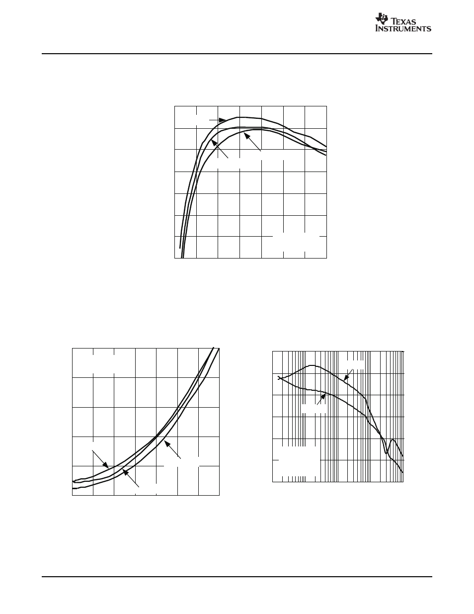
Power Up/Down Test Procedures
81
79
87
83
91
89
93
85
2
6
18
26
22
10
14
I
OUT
- Output Current - A
V
IN
= 36 V
V
IN
= 72 V
V
IN
= 48 V
P
e
rc
e
n
t
E
ff
ic
ie
n
c
y
-
%
V
OUT
= 3.3 V
f
S
= 300 kHz
OVERALL EFFICIENCY
vs
OUTPUT CURRENT
10
-40
-60
100
1 k
10 k
100 k
0
-20
40
20
60
-120
-180
0
-60
120
60
180
V
IN
= 36 V
I
OUT
= 10 A
g
M
= -8 dB
F
M
= 50°
Gain
Phase
f - Frequency - Hz
G
a
in
-
d
B
P
h
a
s
e
-
°
GAIN AND PHASE
vs
FREQUENCY
4
2
10
6
12
8
6
18
26
30
22
10
14
2
I
OUT
- Output Current - A
V
IN
= 36 V
V
IN
= 72 V
V
IN
= 48 V
P
L
O
S
S
-
P
o
w
e
r
L
o
s
s
-
W
V
OUT
= 3.3 V
f
S
= 300 kHz
POWER LOSS
vs
OUTPUT CURRENT
Power Up/Down Test Procedures
Figure 3.
Figure 5.
Figure 4.
Using the UCC2891 Active Clamp Current Mode PWM Controller
10
SLUU178A – November 2003 – Revised December 2006
See also other documents in the category Texas Instruments Hardware:
- Digital Signal Processor SM320F2812-HT (153 pages)
- MSP430x1xx (440 pages)
- Laser And Motor Drives DRV8811EVM (13 pages)
- TMS320 DSP (88 pages)
- MSP430x11x1 (45 pages)
- TVP5154EVM (55 pages)
- TMS320DM646X DMSOC (64 pages)
- CC2511 (24 pages)
- SN65HVS880 (4 pages)
- TPS650231EVM (14 pages)
- TMS320TCI648x (256 pages)
- TSC2007EVM-PDK (16 pages)
- UCC38500EVM (16 pages)
- TMS320C6000 (62 pages)
- SCAU020 (21 pages)
- TPS40051 (17 pages)
- TNETE2201 (14 pages)
- TMS320C64x DSP (306 pages)
- TMS320C3x (757 pages)
- MSP430 (138 pages)
- TMS320C6712D (102 pages)
- MSP430x4xx (512 pages)
- TMS320C6454 (225 pages)
- SPRU938B (48 pages)
- TUSB3210 (22 pages)
- TMS320C6457 (43 pages)
- CC2530ZNP (3 pages)
- TMS320C6455 (50 pages)
- TSB12LV26 (91 pages)
- TMS320C6472 (2 pages)
- VLYNQ Port (49 pages)
- TMS380C26 (92 pages)
- MSP-FET430 (95 pages)
- TMS320TCI6486 (160 pages)
- TPS2330 (22 pages)
- DM648 DSP (47 pages)
- TMS320DM36X (134 pages)
- MSC1211 (35 pages)
- SPRAA56 (29 pages)
- DAC7741EVM (28 pages)
- CDCM7005 (34 pages)
- TMS370 (99 pages)
- Adpater (37 pages)
- TMS320C6452 DSP (46 pages)