2 pcb key map – Texas Instruments TAS5110D6REF User Manual
Page 11
PCB Key Map
1-3
Introduction
1.2
PCB Key Map
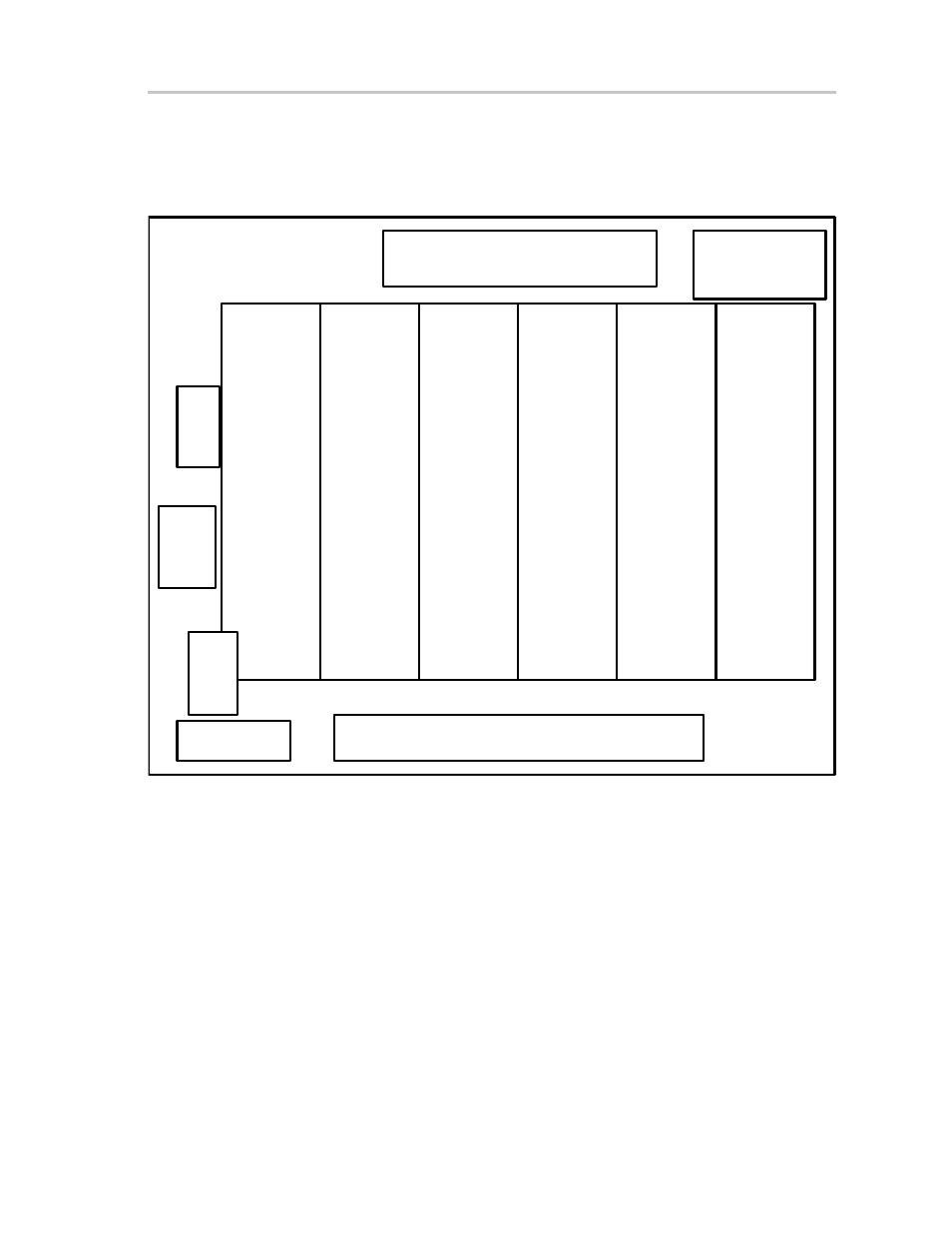
The physical structure for the TAS5110D6REF is illustrated in Figure 1–2.
Figure 1–2. Physical Structure for the TAS5110D6REF (Rough Outline)
J110
Subwoofer Output
(Line Level)
J240, J280, J340, J380, J440, and J480
Loudspeaker Outputs
J100
PWM Interface
J160
PSU Control
Interface
J150
3.3-V Linear
Regulator
LED Indicators
Output Stage Channel 1
Left Front Speaker
Output Stage Channel 2
Right Front Speaker
Output Stage Channel 3
Left Rear Speaker
Output Stage Channel 4
Right Rear Speaker
Output Stage Channel 5
Center Speaker
Output Stage Channel 6
Subwoofer
TAS5110D6REF
PSU Interface
See also other documents in the category Texas Instruments Receivers and Amplifiers:
- THS4151 (26 pages)
- TRF1500 (74 pages)
- SLOU082 (28 pages)
- TAS5508-5121K8EVM (24 pages)
- TPA6102A2 (16 pages)
- TPA3001D1EVM (22 pages)
- TPA6030A4 (25 pages)
- TPA701 (26 pages)
- TPA6110A2 MSOP (18 pages)
- TAS5727 (21 pages)
- THS4503EVM (28 pages)
- TPA005D02 (50 pages)
- SLOU121 (42 pages)
- TPA0243 (20 pages)
- TPA0253 (20 pages)
- TPA102 MSOP (26 pages)
- THS4131 (26 pages)
- SLOU020A (28 pages)
- TPA751 MSOP (20 pages)
- TPA005D12 (44 pages)
- TPA6139A2 EVM (8 pages)
- TPA0103 (32 pages)
- SLOU106 (26 pages)
- THS4141 (26 pages)
- THS3001 (20 pages)
- TPA0233 (20 pages)
- TPA2008D2 (26 pages)
- 2004 (20 pages)
- TPA3003D2 (36 pages)
- SLAU081 (44 pages)
- TPA301 (28 pages)
- TPA3100D2 (11 pages)
- SLOU023A (26 pages)
- TA5704EVM (27 pages)
- TAS5518 (20 pages)
- APA100 (42 pages)
- TPA3200D1 (30 pages)
- TAS5066PAG (22 pages)
- TPA6204A1 (16 pages)
- THS4150 (26 pages)
- TPA311 (28 pages)
- TPA3008D2 (31 pages)
- TPA6101A2 (16 pages)