When two or more inverters are connected – Toshiba TOSVERT VF-S15 series option unit Function E6581830 User Manual
Page 50
E658130
- 49 -
2.When two or more inverters are connected
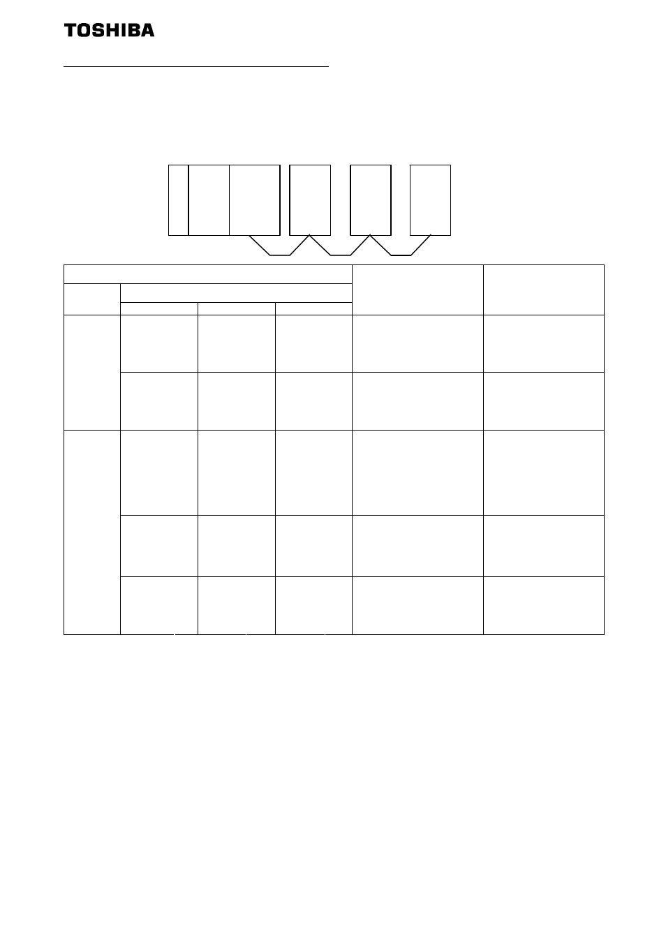
The following example explains the causes and corrective actions for fault which may be
judged from the LED status of the CC-Link units (CCL003Z) of the inverters under the
condition that the SW, M/S and PRM LEDs of the master unit are off (the master unit setting is
proper) in the system configuration shown below:
PS:
Power
supply
LED Status
CCL003Z
Master
Station
1 Station
2 Station
3
Cause Corrective
Action
L.RUN
●
L.RUN
●
L.RUN
●
SD
●
SD
●
SD
●
RD
●
RD
●
RD
●
L.ERR
○
L.ERR
○
L.ERR
○
Normal
-
L.RUN
○
L.RUN
●
L.RUN
●
SD
○
SD
●
SD
●
RD
○
RD
●
RD
●
TIME○
LINE○
or
TIME●
LINE○
L.ERR
○
L.ERR
○
L.ERR
○
Poor contact of the
CCL003Z with the
Inverter or the power
supply is not supplied.
Plug the CCL003Z
securely.
Check the connector.
L.RUN
●
L.RUN
○
L.RUN
○
SD
●
SD
*
SD
*
RD
●
RD
*
RD
*
L.ERR
○
L.ERR
○
L.ERR
○
Since the L.RUN LEDs
of station 2 and later are
off, the communication
cable between the unit 1
and 2 is open or
disconnected from the
terminal block.
Referring to the LED
"on" condition, search
for an open point and
repair.
L.RUN
○
L.RUN
○
L.RUN
○
SD
*
SD
*
SD
*
RD
*
RD
*
RD
*
L.ERR
○
L.ERR
○
L.ERR
○
The communication
cable is shorted.
Among the three wires
of the communication
cable, search for
shorted wire and
repair.
L.RUN
○
L.RUN
○
L.RUN
○
SD
*
SD
*
SD
*
RD
*
RD
*
RD
*
TIME●
LINE●
or
TIME○
LINE●
L.ERR
*
L.ERR
*
L.ERR
*
The communication
cable is wired improperly.
Check the wiring on
CCL003Z terminal
block and correct the
improper wiring point.
●
:
On,
○:
OFF, ◎:
Flicker,
*:
Any of on, flicker or off.
Master
CPU Unit
Station
1
Inverter
P
S
Station
2
Inverter
Station
3
Inverter