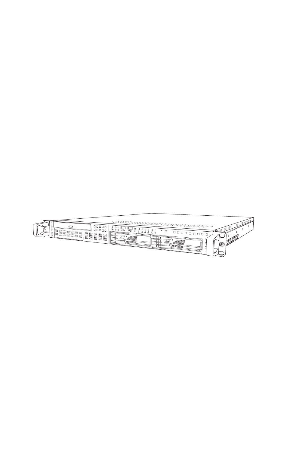
Tyan Computer GX21 User Manual
Tyan Computer Computer Accessories
This manual is related to the following products:
Table of contents
Document Outline
- Chapter 1: Overview
- Chapter 2: Setting Up
- 2.1 Before You Begin
- 2.2 Rack Mounting
- 2.2.1 Installing the Server in a Rack
- 1. Screw the mounting ears to the Transport GX21 as shown using 4 screws from the supplied nuts, screws and washers kit.
- 2. Screw the sliding rail mounting brackets to the sliding rails as shown, using the short black screws from the supplied nuts, screws and washers kit. Ensure that the brackets with the cut away section (to accommodate the handles on the fron...
- 3. Fully extend the sliding rails until they lock.
- 4. Screw each sliding rail to the side of the Transport GX21 as shown. You will need 3 short, silver colored screws from the supplied nuts, screws and washers kit, for each rail.
- 5. Return the sliding rails to their shortest position.
- 6. With the rails in their shortest condition, adjust both front mounting brackets so that they are flush with the front of the unit.
- 7. Accurately measure the depth of your rack and adjust the rear brackets accordingly.
- 8. When all brackets are positioned correctly, tighten them.
- 9. Lift the unit into place in the rack and screw it into place as shown.
- 2.2.1 Installing the Server in a Rack
- 2.3 Installing Motherboard Components
- 2.3.1 Removing the Chassis Cover
- 2.3.2 Installing a CPU, Heatsink and Air Duct
- 1. Remove the pre-installed air duct. Refer to the illustration on top of the air duct to locate the 2 screws.
- CPU socket under air duct
- Pin 1
- 4. Press the CPU socket lever down in the direction shown to secure the CPU.
- 5. Apply thermal grease to the top of the CPU and place the CPU heatsink on the CPU.
- 6. Align the heatsink screw holes with the holes on the motherboard and insert the four heatsink screws as shown.
- 7. Place the air duct over the heatsink and replace the heat shield screws to secure it to the motherboard.
- 2.3.3 Installing Memory
- 2.3.4 Installing a PCI Card
- 1. Remove the pre-installed PCI retention bar
- PCI riser card
- 2. Remove the screw securing the PCI faceplate to the chassis.
- 3. Slide the PCI card clamp out as shown.
- 4. Slide the dust cover out.
- 5. Slide the PCI card into place and then insert it into the PCI slot on the riser card. Ensure that it is inserted cor rectly.
- 6. Reinsert the PCI card clamp.
- 7. Insert the screw to secure the PCI card to the chassis.
- 2.4 Installing a Hard Drive
- 2.4.1 Installing an External Access S-ATA Hard Disk Drive
- 1. Press the drive bay locking lever latch in the direction of the arrow (1) and pull the locking lever open (2).
- 2. Slide the drive bay out.
- 3. Place an S-ATA hard drive into the drive bay.
- 4. Insert hard drive screws to secure the hard drive to the drive bay.
- 5. Reinsert the drive bay into the chassis, ensuring that the HDD rear connector is securely connected to the back plane connector.
- 2.4.2 Installing an Internal IDE or S-ATA Hard Disk Drive
- 1. Remove the IDE or S-ATA data cable and power connec tor from the HDD.
- 2. Remove the screw securing the HDD tray to the chassis.
- 3. Slide the HDD tray out.
- 4. Place an IDE or S-ATA HDD into the tray, and secure with 4 screws.
- 5. Reinsert the HDD tray and secure with a screw.
- 6. Connect the IDE or S-ATA data cable and power cable connector to the HDD.
- 2.4.1 Installing an External Access S-ATA Hard Disk Drive
- Chapter 3: Replacing Pre-Installed Components
- 3.1 Introduction
- 3.2 Disassembly Flowchart
- 3.3 Removing the Cover
- 3.4 Replacing Motherboard Components
- 3.5 Replacing the CD-ROM/FDD
- 1. Remove the data cable from the slim CD-ROM adapter.
- 2. Remove the power cable from the slim CD-ROM adapter.
- 3. Remove the 2 screws that secure the adapter board to the slim CD-ROM and lift it free from the chassis.
- 4. Remove the 4 screws securing the drive bay to the chas sis.
- 5. Lift the drive bay free from the chassis.
- 6. Remove the 4 small screws securing the CD-ROM or FDD in the drive bay.
- 7. Slide the CD-ROM or FDD from the drive bay.
- 3.6 Replacing the FDD with a HDD
- 1. Remove the power and data cables from the back of the CD-ROM drive and FDD.
- 2. Remove the 4 screws that secure the drive bay housing to the chassis.
- 3. Slide the drive bay housing backwards and lift it clear of the chassis.
- 4. Remove the 4 screws that secure the FDD in the drive bay and lift it free of the drive bay housing.
- 5. Place a HDD in the drive bay housing and secure with 4 screws. Refer to section 2.4.2 Installing an Internal IDE or S-ATA Hard Disk Drive for details on installing a hard disk.
- 6. Replace the drive bay housing in the chassis and secure with 4 screws.
- 7. Replace the power and data cables for the CD-ROM drive and the new HDD unit.
- 3.7 Replacing the LED Control Board
- 1. Remove the 2 screws securing the metal retaining plate to the chassis.
- 2. Lift the retaining plate free of the chassis, as shown below.
- 3. Unplug the front panel ribbon cable connector from the rear of the LED control panel.
- 4. Unplug the other end of the ribbon cable from the back plane of the HDD as shown...
- 5. Lift the ribbon cable free from the chassis.
- 6. Remove the 2 screws securing the LED control board to the chassis.
- 7. Lift the LED control board free from the chassis.
- 3.8 Replacing the S-ATA Backplane
- 1. Remove the 2 screws securing the metal retaining plate to the chassis and lift the retaining plate free.
- 2. Remove the cables from the rear of the S-ATA back plane.
- 3. Remove the 5 screws that secure the backplane bracket to the chassis.
- 4. Lift the backplane bracket free from the chassis as shown
- 3.8.1 2 Port S-ATA Backplane Features
- 3.9 Replacing the Power Supply
- 1. Remove the 4 screws that secure the fan assembly to the chassis.
- 2. Lift the fan assembly clear to give access to the power supply cables.
- 3. Remove power cables from the motherboard, HDDs and FDD if installed.
- 4. Remove the 2 screws from the mounting bracket that secure the power supply to the chassis.
- 5. Remove the 2 screws from the power supply rear bracket that secure it to the chassis.
- 6. Lift the power supply clear of the chassis.
- 7. Remove the 2 screws that secure the power supply bracket to the power supply and remove the bracket.
- 3.10 Replacing the Cooling Fans
- 1. Remove all the cooling fan power supply cables.
- 2. Remove the 2 screws which secure the cooling fan bracket to the chassis.
- 3. Lift the cooling fan assembly from the chassis.
- 4. Remove the 4 screws that secure each cooling fan to the cooling fan bracket.
- 5. Lift the cooling fan clear of the bracket.
- 6. Repeat step 5 until all the necessary cooling fans have been removed from the cooling fan bracket.
- Appendix
- BIOS Setup
- Installation
- BIOS Setup - Main Screen
- Standard CMOS Features
- Advanced BIOS Features
- Virus Warning
- CPU L1 & L2 Cache
- Hyper-Threading Technology
- Quick Power On Self Test
- Boot Sequence
- Bootup NumLock Status
- Gate A20 Option
- Typematic Rate Setting
- Typematic Rate (Chars/Sec)
- Typematic Delay (Msec)
- Security Option
- APIC Mode
- MPS Version Control For OS
- OS Select For DRAM > 64MB
- HDD S.M.A.R.T. Capability
- Report No FDD For WIN 95
- Small Logo (EPA) Show
- Advanced Chipsets Features
- Integrated Peripherals
- OnChip IDE Device
- IDE HDD Block Mode
- On-Chip Primary PCI IDE
- Primary / Secondary Master/ Slave PIO
- Primary / Secondary Master/ Slave UDMA
- On-Chip Serial ATA
- Onboard Device
- USB Controller
- USB 2.0 Controller
- USB Keyboard Support
- USB Mouse Support
- Onboard Promise RAID Ctrl
- CSA LAN (GbE LAN)
- Super IO Controller
- Onboard FDC Controller
- Onboard Serial Port 1 / 2
- UART Mode Select
- RxD, TxD Active
- IR Transmission Delay
- UR2 Duplex Mode
- Onboard Parallel Port
- Parallel Port Mode
- EPP Mode Select
- ECP Mode Use DMA
- Power Management Setup
- ACPI Function
- Power Management Option
- Video Off Method
- Video Off In Suspend
- Suspend Type
- MODEM Use IRQ
- Suspend Mode
- HDD Power Down
- CPU THRM-Throttling
- Power On Setup
- PWRON After PWR-Fail
- Soft-off by PWR-BTTN
- Wake Up by PCI Card
- Power on by Ring
- Power on by Giga Lan
- Resume by Alarm
- POWER ON Function
- KB Power ON Password
- Hot Key Power ON
- Reload Global Timer Events
- PnP/PCI Configurations
- Reset Configuration Data
- Resources Controlled By
- PCI / VGA Palette Snoop
- PCI 1 INT Assignment
- CNR LAN INT Assignment
- Promise S-ATA INT Assignment:
- Intel i541 INT Assignment:
- PC Health Status
- Frequency/Voltage Control
- Load Optimized Defaults
- Supervisor/User Password Setting
- Save & Exit Setup
- Exit Without Saving