Installation – Tripp Lite B042-008 User Manual
Page 4
4
2. Installation
2.1 Mounting the NetController KVM Switch
2.2 Connecting Your PCs and Peripherals to a Single NetController KVM Switch
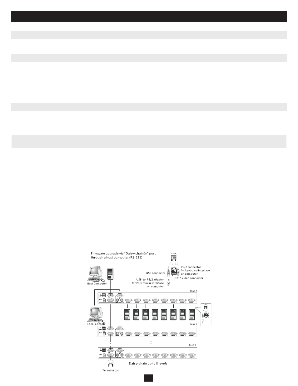
2.3 Daisy-Chaining B042-Series KVM Switches
The KVM Switch can be placed on a desktop or mounted in a standard 19” rack.
Step 1: Connect the console (shared USB or PS/2 keyboard, mouse and monitor) to the console connectors on the backside of the KVM Switch.
Note: For USB connection, separate keyboard and mouse connectors are required.
Step 2: Connect the included 9V DC power adapter cord to the KVM Switch to power it on.
Step 3: Connect each computer to the KVM Switch using a P780-Series Tripp Lite USB PS/2 KVM Cable Kit. Not included.
The KVM Switch is now ready to operate as soon as you turn on any of the attached computers.
Note: When you are connecting a PS/2 computer, it is required that the B042-004,-008 or -016 KVM Switch is connected and powered on before starting your computers.
To maximize the number of connected computers, multiple B042-004,-008 or -016 KVM Switches can be daisy-chained together to connect up to a total
of 128 computers (with 8 units of the B042-016 KVM Switch). The B042-Series KVM Switches that are to be daisy-chained do not have to be of the same
port capacity. You can daisy-chain any combination of B042-004,-008 or -016 KVM Switches to scale the port capacity with more flexibility. KVM controls
can then be extended to groups of computers connected on the daisy-chain of B042-Series KVM Switches.
Warning! The total length of daisy-chain cabling from the master KVM switch to the last KVM switch in a daisy-chain installation (regardless of the
number of levels) must not exceed 16 ft. (5 m). If the total length of daisy-chain cabling exceeds 16 ft. (5 m), the installation will not function properly.
Daisy-Chain Multiple KVM Switches
Step 1: Connect the console (shared USB or PS/2 keyboard, mouse and monitor) to the console port connectors on the rear panel of the master (first)
B042-Series KVM Switch, or use a Tripp Lite B040-series KVM Switch with built-in console.
Step 2: Connect the power adapter cord to the DC 9V power receptacle on the master KVM Switch and plug it in to a power source.
Step 3:
Use the provided daisy-chain cable—HD15 (M) to HD15 (F)—to connect the daisy-chain OUT port of the master KVM switch to the
daisy-chain IN port of the second (downstream) B042-004,-008 or -016 KVM Switch. Then connect the power adapter cord to the 9V DC
power receptacle on the second KVM Switch.
Step 4: Follow the same procedure for any additional KVM Switches you would like to attach, creating a daisy-chain up to 8 KVM Switches.
Step 5:
After you have set up the Daisy-Chain of KVM Switches, plug the daisy-chain terminator into the daisy-chain OUT port of the last
KVM Switch.
Step 6: Connect each computer to the KVM Switches in your daisy-chain using a P780-series Tripp Lite USB PS/2 KVM Cable Kit. Not included.
Step 7: The KVM Switches are now ready to operate as soon as you turn on any of the attached computers.
Note: When you are connecting a PS/2 computer, it is required that the B042-004,-008 or -016 KVM Switch is connected and powered on before starting your computer.
* It is not necessary to attach the daisy-chain terminator if you are not daisy-chaining the switch to another KVM.
Figure 2: Daisy-Chain Diagram
Warning! Total daisy-chain cabling distance from the master KVM switch
to the last KVM switch must not exceed 16 ft. (5 m).