Configuration, Set configuration dip switches, Group a dip switches (all models) – Tripp Lite TMU Series User Manual
Page 6
6T
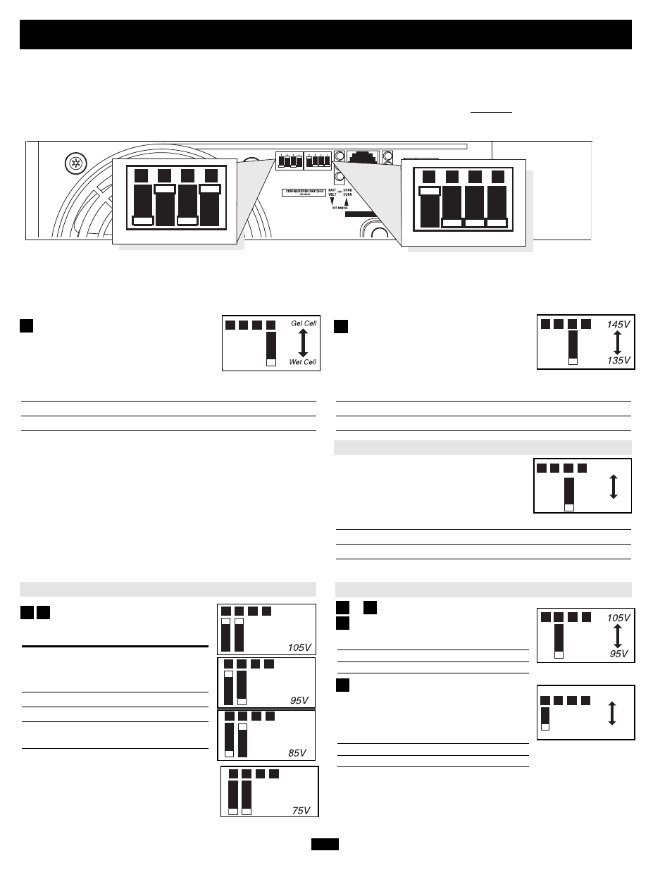
Select Battery Type—REQUIRED
(All models)
CAUTION: The Battery Type DIP Switch setting must match
the type of batteries you connect, or your batteries may be
degraded or damaged over an extended period of time. See
“Battery Selection,” p. 9 for more information.
Battery Type
Switch Position
Gel Cell (Sealed) Battery
Up
Wet Cell (Vented) Battery
Down (factory setting)
Select High AC Input Voltage Point
for Switching to Battery—OPTIONAL*
(All models except TMU1250)
Voltage
Switch Position
145V
Up
135V
Down (factory setting)
Select Charger Enable/Inhibit
Status
Switch Position
Inhinit
Up
Enable
Down (factory setting)
Configuration
Set Configuration DIP Switches
Using a small tool, set the Configuration DIP Switches (located on the front panel, see diagram) to optimize UPS System operation, depend-
ing on your application. TMU612 models include one set of four DIP Switches. All other models include an additional set of four DIP switches to
configure additional operational functions. Refer to the appropriate section to review the instructions for your specific model.
A1
A2
A3
A4
A1
A2
A3
A4
INPUT C/B 10A
OUTPUT C/B 12A
B4
B3
B2
B1
A4
A3
A2
A1
Group B Dip Switches (Not on 612 Models)
Group A Dip Switches (All Models)
Group A DIP Switches (All Models)
Using a small tool, configure your UPS System by setting the four Group A DIP Switches (located on the front panel of your unit; see dia-
gram) as follows:
A1
A2
* Most of your connected equipment will perform adequately when your UPS System’s High AC Input Voltage Point (DIP Switch #2 of Group A) is set to 135V and its Low AC Voltage Input Point (DIP Switches #3 and #4 of Group A or DIP Switch #3 for 612 models) are set
to 95V. However, if the unit frequently switches to battery power due to momentary high/low line voltage swings that would have little effect on equipment operation, you may wish to adjust these settings. By increasing the High AC Voltage Point and/or decreasing the Low AC
Voltage Point, you will reduce the number of times your unit switches to battery due to voltage swings.
Select Low AC Input Voltage
Point for Switching to Battery—
OPTIONAL*
Switch
Voltage
Position
105V
#A4 Up & #A3 Up
95V
#A4 Up & #A3 Down
85V
#A4 Down & #A3 Up
75V
#A4 Down & #A3 Down
(factory setting)
A1
A2
A3
A4
A1
A2
A3
A4
A1
A2
A3
A4
A1
A2
A3
A4
A3
A4
A1
A2
A3
A4
High Charge Amp
Low Charge Amp
A1
A2
A3
A4
A3
A4
A3
Set Battery Charging Amps Type—OPTIONAL
Check specifications on for your unit’s high- and low-charging
amp options. By setting on high charging, your batteries will
charge at maximum speed. When setting on low charging, you
lengthen the life of your batteries (especially smaller ones).
Battery Charger
Switch Position
High Charge Amp
Up
Low Charge Amp
Down (factory setting)*
A4
Select Low AC Input Point for Switching to
Battery—OPTIONAL
Voltage
Switch Position
105V
Up
95V
Down (factory setting)
&
Settings
TMU612 Only
All Models Except TMU612
A1
A2
A3
A4
Enable
Inhibit
TMU1250 Only