Telos Zephyr Xport User Manual
Page 50
ZEPHYR
XPORT
USER’S GUIDE
40
CHAPTER 6 - T ECHNICAL & INSTALLATION IFNORMATION
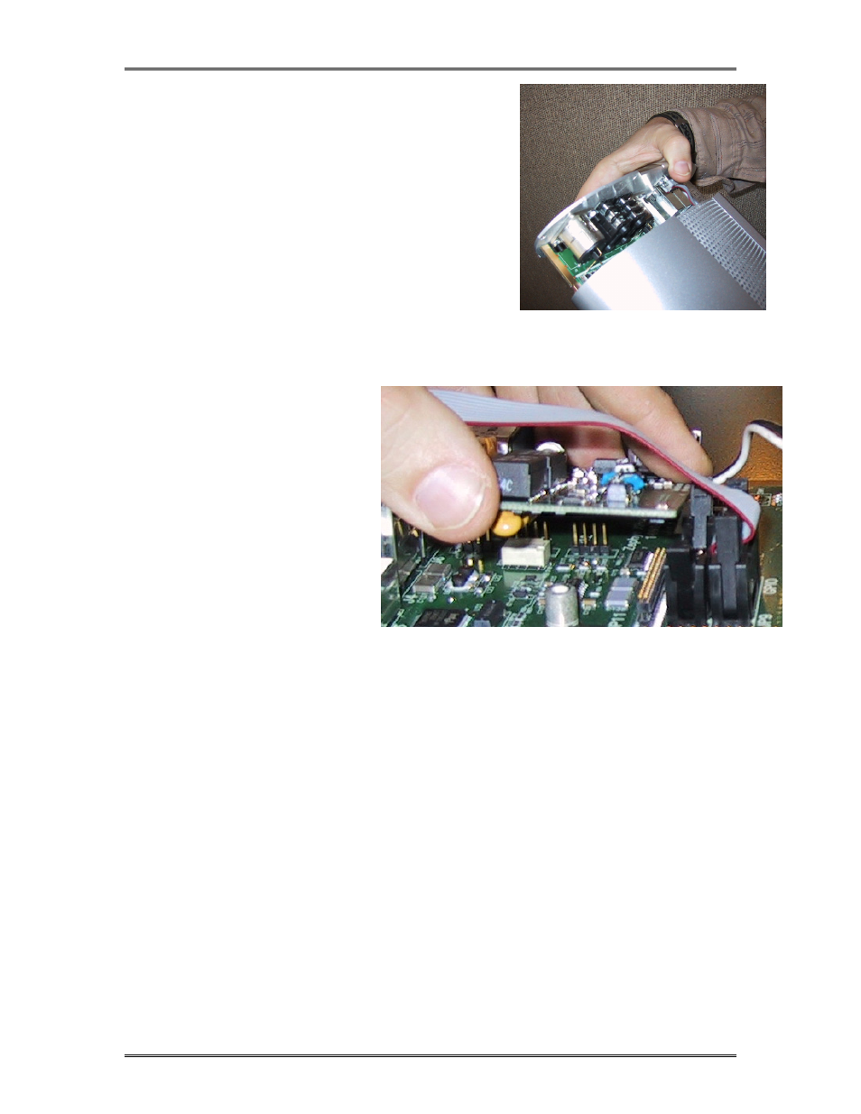
6. Note the standoff near JP 11 and headers
JP6, JP7, and JP12 et al. Remove the screw
(and washer) from the standoff.
7. Plug in and fasten the ISDN card in as
follows (see below):
•
Orient the Xport circuit board so that
the rear panel is to your left.
•
Orient the ISDN option board so that
the sockets labeled JP1, JP2 and JP4 are
away from you and facing down.
•
With the ISDN card angled up so that you can see, make a preliminary
alignment of sockets JP1, JP2 and JP4 of the isdn board to headers JP12, JP7 and
JP6 on the motherboard, respectively (see below).
You may need
to push the
leads to the
power supply
down and out
of the way.
Now tilt the
board down
level and push
down the
board down
onto headers
JP12, JP7, and
JP6.
•
Push down
above socket JP3 of the ISDN card firmly, seating it with header JP 11 on the
motherboard. You should feel the ISDN card snap into place.
•
Replace the screw and washer removed in step 6, above, to lock the ISND card
in place. Tighten with moderate pressure.
8. Re- attach the green wire removed in step 5 to the power entry module.
9. Carefully align the front edges of the circuit board with the lower pair of grooves on
the inside of the case, and carefully slide the circuit board into the chassis. If you
encounter resistance, remove the board, check the alignment, and repeat.
10. Replace the 6 screws removed in step 3
11. Replace the bumper removed in step 2.
12. To configure and test your ISDN Xport please refer to Section 3.4