1 connecting the tas5727evm to mc57xxpsia, 2 psu interface, 3 loudspeaker connectors – Texas Instruments TAS5727 User Manual
Page 4
Installation
2.1.1
Connecting the TAS5727EVM to MC57xxPSIA
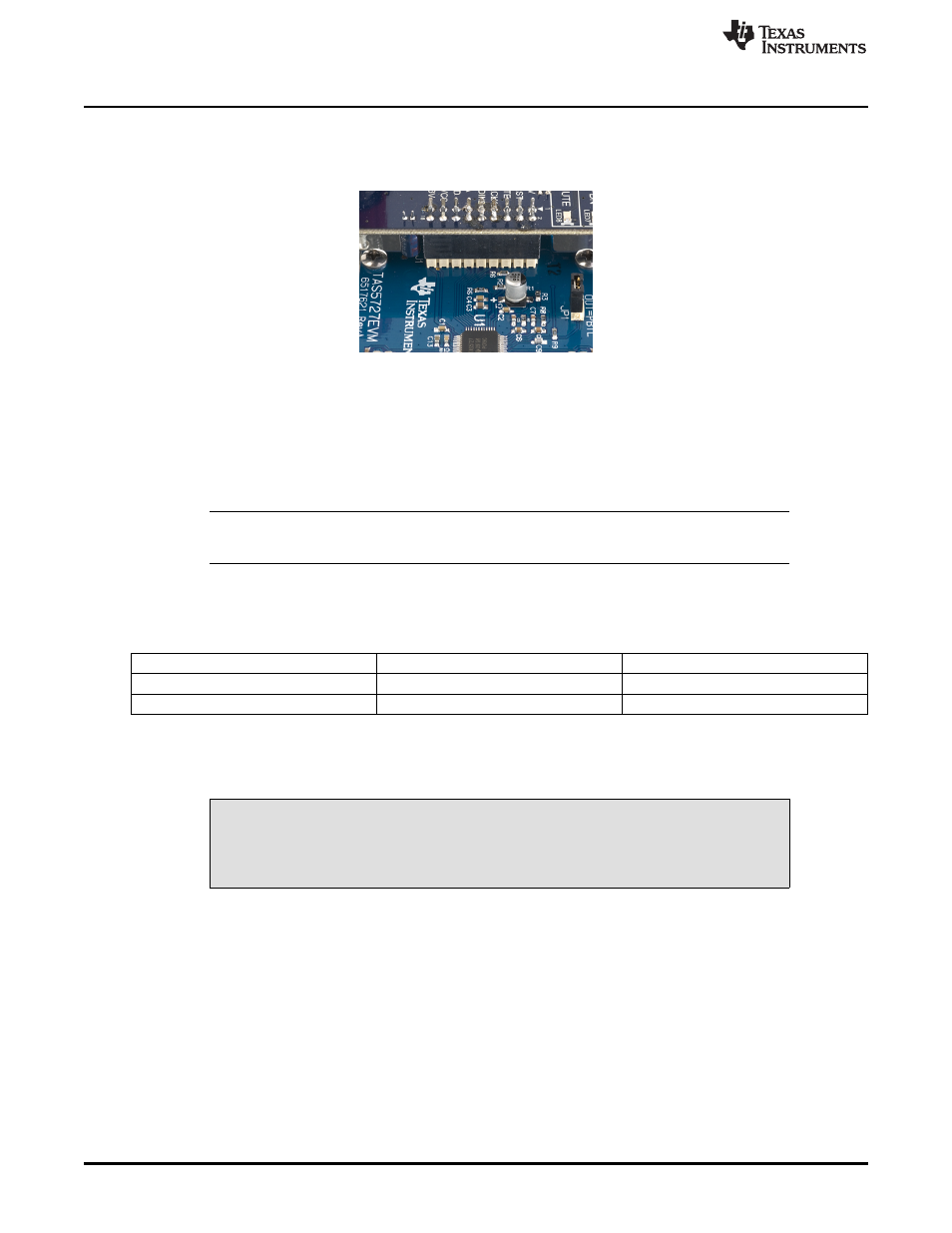
On the right side of the MC57xxPSIA is a terminal block and another on the left of the TAS5727EVM
(labeled J1). Carefully place the MC57xxPSIA block above the TAS5727EVM block and gently push down.
Figure 4. Connecting TAS5727EVM to MC57xxPSIA
2.1.2
PSU Interface
The TAS5727EVM is powered by two power supplies connected to the MC57xxPSIA controller board: a
5V power supply (VIN), and a 8V-to-26V (PVDD) power supply. The 3.3V level is generated from the 5V
supply by an on-board voltage regulator.
NOTE:
The power-supply cable length must be minimized. Increasing the length of the PSU cable
increases the distortion of the amplifier at high output levels and low frequencies.
The maximum output-stage supply voltage depends on the speaker load resistance. See the
recommended maximum supply voltage in the TAS5727EVM data sheet.
Table 1. Recommended Power Supplies
Description
Voltage Limitations (8-
Ω
Load)
Current Recommendations
System power supply
5V
1A
Output power stage supply
8
–
26V
4A
(1)
(1)
The rated current corresponds to two channels, full scale.
2.1.3
Loudspeaker Connectors
CAUTION
All speaker outputs are biased at Vcc/2 and must not be connected to ground
(e.g., through an oscilloscope ground).
Loudspeaker connections vary by device setup. When connecting a speaker in BTL mode, connect the
speaker
’
s two terminals (A and B or C and D) across two outputs on the TAS5727EVM.
Speakers or loads can be connected to the outputs A-D with clip leads, or cables can be made
with female connectors (JST VHR-2N) that can mate to male connectors on the EVM board.
4
TAS5727 25W Digital Input Amplifier
—
with EQ and 2-Band DRC
SLOU299
–
December 2010
Copyright
©
2010, Texas Instruments Incorporated