5 - control panel, Settings tab, Control protocol – Tascam FW-1082 User Manual
Page 26: Clock source, Sample rate, Audio latency, Coax output source, Master fader affects anlg l:r gain, 5 – control panel, 5 –control panel
26
TASCAM FW-1082 Owner’s Manual
5 – Control Panel
The FW-1082’s Control Panel is where you can dis-
play and adjust settings which determine how the
FW-1082 communicates with your computer and
other external devices. To open the Control Panel,
press the
CONTROL PANEL
shortcut key on the FW-
1082’s control surface.
You can also open the Control Panel in Windows by
clicking on
Start
–
Control Panel
and selecting
the
FW-1082 Control Panel
icon. Under OS X, the
FW-1082 Manager
can be found in
Applications
.
There are three tabs on the Control Panel:
Settings
,
MIDI Programming
and
Quick Start
.
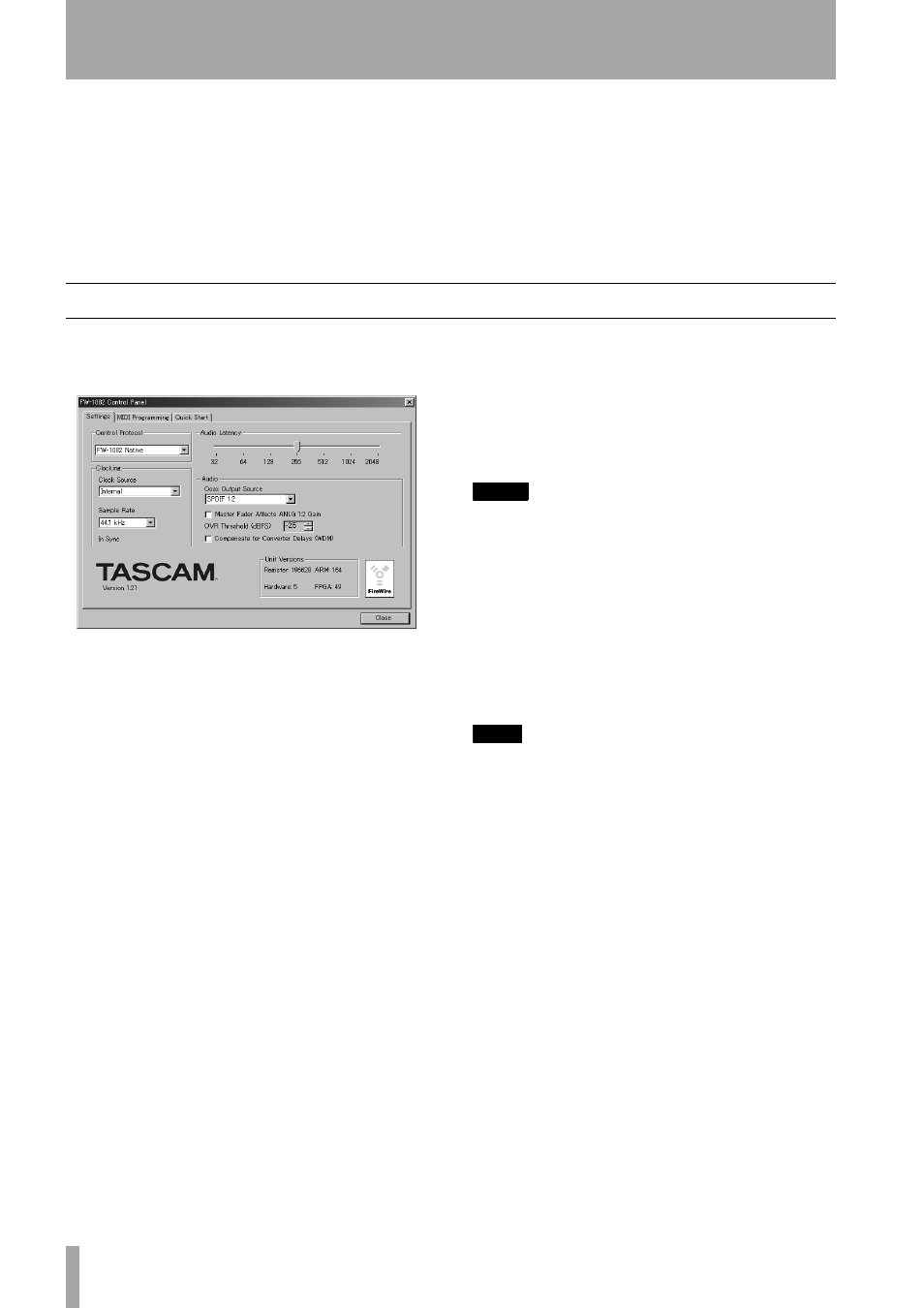
Settings tab
This is where you make the basic settings to config-
ure the FW-1082.
Control Protocol
This is where you select how
the FW-1082’s MIDI commands are interpreted by
the host software application. You can choose
between the FW-1082’s Native Protocol, Mackie
Control
™ emulation protocol, or Mackie HUI™
emulation protocol and others.
Clock Source
This is where you can select the dig-
ital clock source. It duplicates the clock selection
functions made on the control surface.
Changes made on the FW-1082’s control surface are
immediately reflected in this window. For more
information on this function, refer to “Setting and
checking clock rates” on page 17.
Sample Rate
This is where you select the
expected sample rate to the FW-1082’s digital input
and the internal sampling frequency. It duplicates the
control surface settings.
Changes made on the FW-1082’s control surface are
immediately reflected in this window. For more
information on this function, refer to “Setting and
checking clock rates” on page 17.
Audio Latency
This setting is for selecting the
buffer size of the FW-1082’s audio performance. The
FW-1082’s driver temporarily stores input and output
audio samples in buffers. Larger buffer sizes will pro-
duce higher latencies but will result in greater system
stability, and protection against other system activi-
ties causing clicks, pops and other audio artifacts.
NOTE
Note that if you are using the FW-1082’s
MON
MIX
mode
to monitor your inputs, you will already have zero-
latency monitoring. In this case, we recommend setting
the buffer size to 1024 or 2048 for maximum system sta-
bility.
Coax Output Source
This setting determines
whether the coaxial digital output mirrors the FW-
1082’s analog monitor outputs (
Analog L-R
) or
whether it is independent of them, providing another
pair of outputs (
SPDIF 1-2
).
TIP
By using the S/PDIF outputs sourced from
Analog L-R
,
you can use the
MONITOR
control knob with speakers
with digital inputs.
Master Fader Affects ANLG L:R Gain
The
Master Fader Affects ANLG L:R Gain
switch
determines whether the computer generated audio
sent to the analog outputs will be affected by the
master fader of the FW-1082.
The default setting is OFF.
• Turn this switch on when the DAW application
you're using doesn't process "Master Fader" MIDI
messages originating from the FW-1082 surface. In
this case, the FW-1082's internal mixer will change
the gain of the analog outputs according to the set-
ting of the master fader.
• Leave this switch off when your DAW application
responds to the "Master Fader" MIDI message by
changing the gain of the analog outputs using the
host processor.
Figure 5.1: Settings tab