Specifications, hpr122i – QSC Audio HPR122i User Manual
Page 21
21
Specifications, HPR122i
HPR122i
Frequency Response, -3dB
62-18k Hz
Frequency Range, -10dB
53-22k Hz
Maximum Peak SPL
131dB
Nominal coverage, H x V
75°x75°
Directivity Index
9.7
Directivity Factor
9.4
Transducer Description
12” (309mm) transducer with 3” (76mm) voice coil
1” (25mm) throat compression drive
Acoustic Crossover Freq.
2,000 Hz
Amp Power
400 Watts, low frequency
100 Watts, high frequency
Input Sensitivity
0.775 V
rms
(+0dBu)
Input Headroom/Clipping
10 V
rms
(+22.2dBu)
Input Connector/Impedance
XLR female, 22k Ohm, balanced, line-level input
(unbalanced, 11k Ohm)
Output Connector
XLR male, wired in parallel with Input connector
Controls, Indicators, and
Gain control, 100 Hz low-cut filter switch, Front LED on/off switch, Limit/Clip (red LED), Signal presence (green LED), AC Power (blue LED),
Adjustments
AC Power switch, AC circuit breaker
Protection, Agency certs.
Thermal limiting, On/Off muting, power limiting, DC protection, short circuit protection, ultrasonic protection, RF protection, UL/CE listed
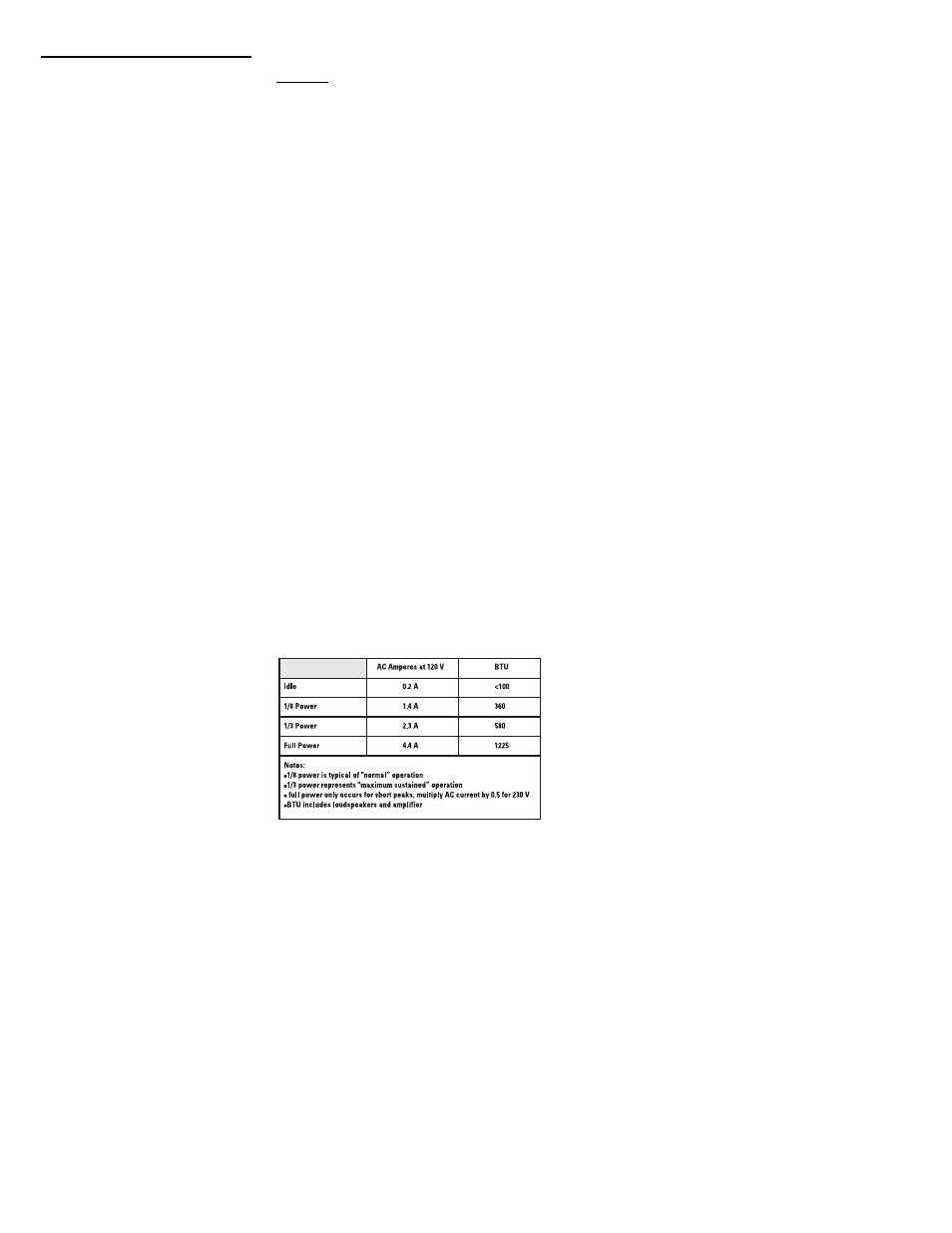
AC Power Requirements
AC Power Connector and Cordset
Factory supplied IEC cordset: 9’ (3m) #18AWG 120V North American or European 230V cordset
Dimensions (height, width, depth)
26.9” (683mm) x 14.7” (373mm) x 14.9” (379mm)
Installation Clearance
Allow for 6.0” (152mm) of free space behind the enclosure to assure proper amplifier cooling
Weight
60 lb/27.2 kg
Finish and Grill
Wear-resistant textured paint finish on plywood enclosure and powder-coated perforated steel grill
Notes:
1- Maximum Peak SPL: Calculated by adding the loudspeaker’s sensitivity (1W at 1m) to the peak power (dBw) of the amplifier provided.
2- Directivity Index (DI): Difference between on-axis SPL and average SPL (considering all axes) for the specified coverage range. DI= 10 log Q
3- Directivity Factor (Q): Directivity index expressed as a power ratio Q=10 exp DI/10
4- Amplifier Power: The maximum sustained power at less than 1% clipping, averaged over the intended frequency range,
5- Input Sensitivity: The sine-wave input voltage required to reach amplifier clipping, measured within the frequency range used to determine Maximum Peak SPL, with the gain on “normal” and no gain reduction
due to limiting.
6- Input Headroom/Clipping: Maximum input voltage.
7- Input Connector/Impedance: RF shunt capacitance should not reduce impedance by more than 30% at 20k Hz.