Separate vent kit installation – QHT Boiler User Manual
Page 15
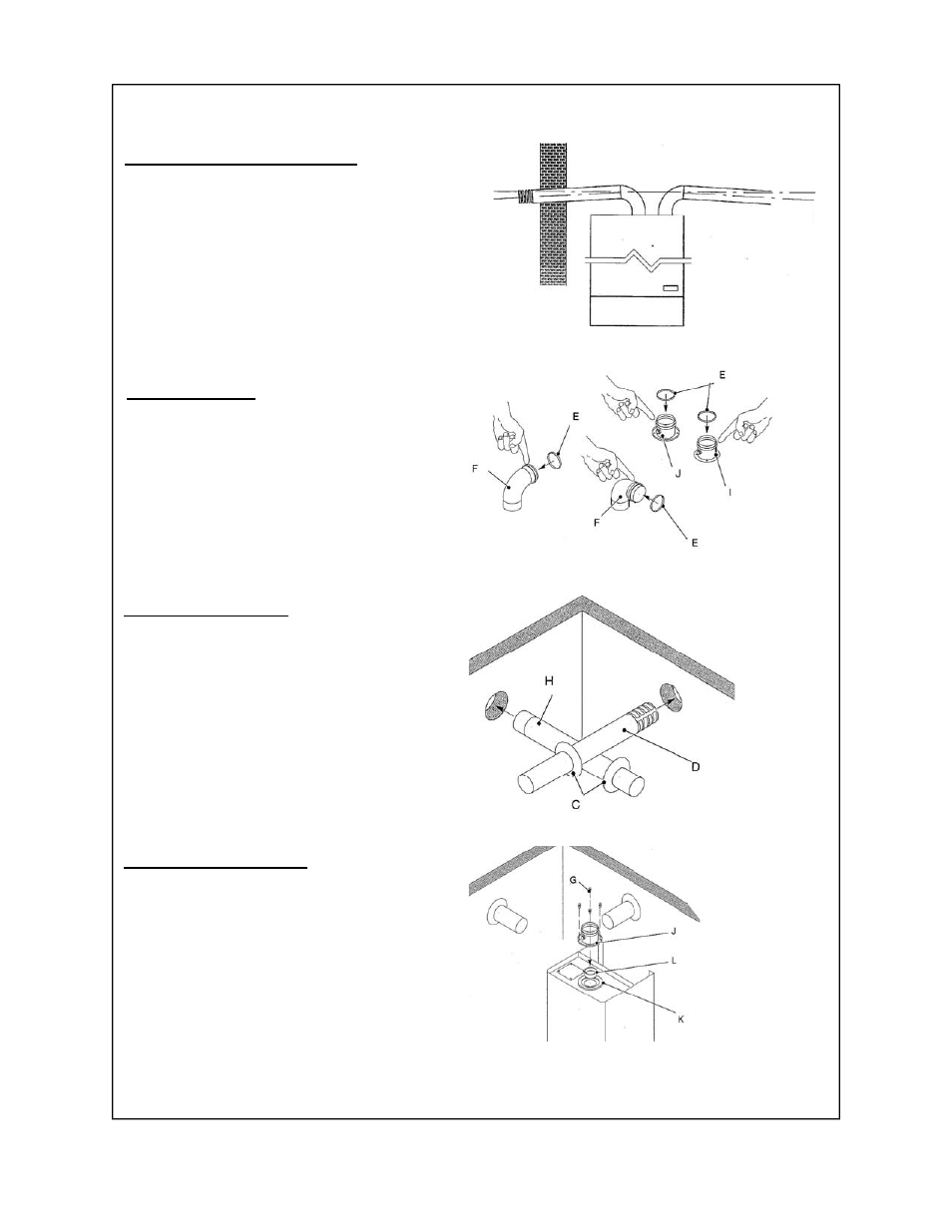
Separate Vent Kit Installation
Figure 1
Figure 2
Termination Location / Installation:
Drill the intake and exhaust holes through the
external wall according to the boiler mounting
diagram supplied in the boiler package. Be
sure to account for the 3° downward pitch
away from the boiler as shown in Figure 1.
Termination Installation :
Install the intake (H) and exhaust (D)
terminations through the corresponding
exterior walls as shown in Figure 3. Slide the
wall gaskets (C) onto each of the pipes to
secure the pipe against the wall.
Figure 4
15
Exhaust Collar Installation :
Mount the exhaust gasket (K) on the exhaust
outlet of the boiler as shown in Figure 4.
Install the appropriate flue restrictor ring (L)
according to the table on page ?. Secure the
Exhaust Collar (J) to the top of the boiler using
the 4 screws (G) supplied.
Figure 3
3° Downward pitch
(2” per 39” length).
Away from boiler
3° Downward pitch
(2” per 39” length).
Away from boiler
Gasket Installation:
Install the gaskets (E) in the exhaust and
intake boiler collars (I,J) and elbows (F), as
shown in figure 2.